Version 4 27 Feb 08
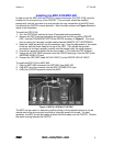
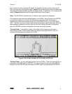
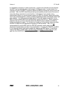
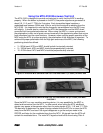
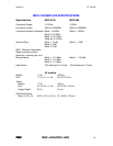
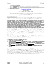
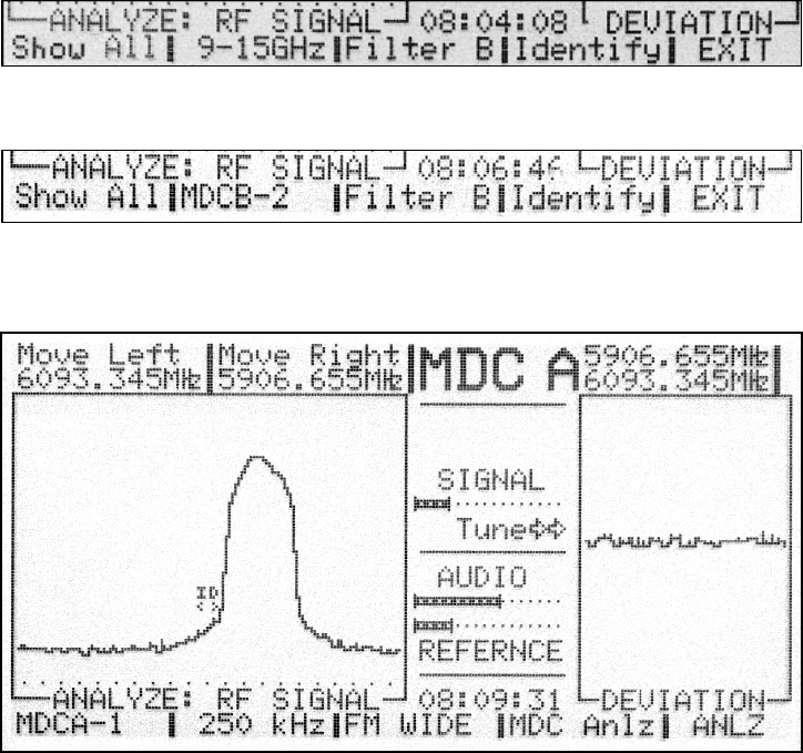
Figure 6A: ANALYZING AN MDC SIGNAL (OSCOR 4.0)
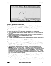
Figure 6B: ANALYZING AN MDC SIGNAL (OSCOR 5.0)
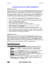
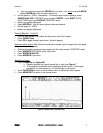
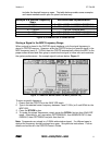
FIGURE 7: USING “IDENTIFY” TO VERIFY A SIGNAL (OSCOR 5.0)
OSCOR Sweep and Analyze Modes with the MDC
In the Sweep mode, the cursor frequency is no longer representative of a single frequency
because of the folding principle described in the introduction of this manual. Therefore,
when the entire frequency spectrum is displayed from 3 to 21GHz (MDC-2100) or 3 to
9GHz (MDC-900), only the local frequency is displayed for the cursor frequency. In this
display, it is important to note that the OSCOR is in the MDC mode and not to confuse this
display with the normal RF/WhipH frequency display. Furthermore, when selecting a
single antenna band as described by Figure 3, the cursor frequency represents four
different possible frequencies (two if using OSCOR 5.0), and when a specific filter is
selected (A or B) then the cursor frequency represents two different possible frequencies.
From the sweep mode, it is impossible to tell the exact frequency of the transmitted signal.
Follow the sequence described in the previous paragraph to determine the exact
transmitted frequency.
Furthermore, when rolling the cursor rotary dial back and forth, half of the numbers
representing potential signal frequencies will be increasing while others will be
decreasing. This again is due to the down-conversion process. Furthermore, often
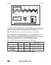
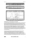
signals will have an odd shape due to the down conversion. In Figure 8, a signal is
selected using the OSCOR NARROW button and the OSCOR rotary dial. This signal has
a rather strange shape because of the folding process of the down-conversion, but it
provides an excellent indicator for the proper signal down conversion. Hence, by pressing
REI MDC-2100/MDC-900 8


