


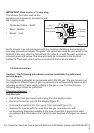
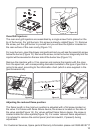
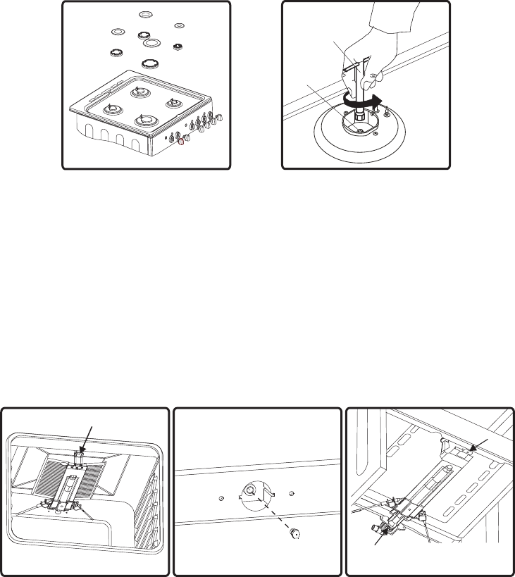
Oven/Grill Injectors
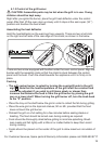
The oven and grill injectors are assembled by a single screw that is placed on the
tip of the burner. For grill burners, this screw is already visible(Figure 11). Remove
the screw, pull the grill burner to yourself and you will see the injector revealed on
the rear surface of the oven cavity (Figure 12).
For oven burners, open the drawer compartment and you will see the assembly screw
below the burner (Figure 13). Remove the screw, move the burner diagonally and the
injector will be revealed on the rear side of the burner box (Figure 12).
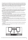
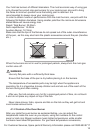
Remove the injectors with a 7mm spanner and replace the injector with the ones
from the spare set, with corresponding diameters suitable to the type of gas that is
going to be used, according to the information chart (which is also supplied in the
gas conversion kit).
:
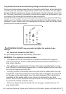
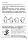
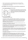
Adjusting the reduced flame position
The flame length in the minimum position is adjusted with a flat screw located on
the valve. For valves with flame failure device, the screw is located on the side of
the valve spindle(Figure 14). For valves without flame failure device, the screw is
located inside the valve spindle(Figure 15). For easier reduced flame adjustment,
it is advised to remove the control panel (and microswitch, if present) during
adjustment.
:
Figure 10
Injector
Spanner
Figure 12
Figure 11
Screw
Figure 13
Screw
Injector
Figure 9
For Customer Services, Spare parts & Warranty Information please call 0845 683 8717
10