16
RUNNING THE TUBING
Make the connection to the compressor and RFD after all other connections are
made.
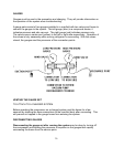
A 1/4" copper tube runs between the compressor unit and the expansion valve. Multiple
plate hook-ups should be assembled as indicated by the specific diagram provided.
A 1/2" line connects the plate outlet to the compressor. If possible run the 1/4" liquid line
in contact with the 1/2” line. This will be insulated in proper sequence. Support the
tubing every 12 to 18 inches as necessary with tie wraps after leak checking and
insulating.
PUMP INSTALLATION
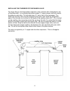
Proper pump installation is important for pump operation. The BG 2000 uses a
centrifugal pump, which is not self-priming. Air pockets caused by loops or descending
lines from one component to the other may cause pump problems. This pump is water
cooled and lubricated, it must never be run dry, doing so will cause the wet end to be
destroyed if it is started or run dry. A separate through hull fitting 3/4" or larger should
be used. The intake should be as low in the boat as possible and away from head and
cockpit drains. A forward facing scoop will prevent problems if the unit is operating
underway.
A large seawater strainer should be mounted above the seacock.
The pump should be mounted horizontally and it should be higher than the strainer.
The discharge should be on the top. Refer to the pump drawing at the back of this
manual.
WARNING: READ SAFETY SECTION BEFORE PROCEEDING
FINAL ASSEMBLY
The RFD contains desiccant to absorb moisture and the compressor oil is hydroscopic
therefore it is important to open the compressor and RFD fittings after all other
connections are made and the system is ready to be commissioned.
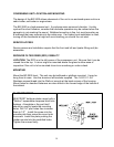
The BG 2000 unit is shipped with some nitrogen pressure. Before removing the caps
on the connection ports remove the screw caps on the access valves and depress the
cores with a clean retracted pen point to vent any existing pressure.
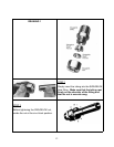
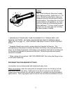
After depressurizing, working with one connection at a time, remove the Swagelok caps
from compressor and liquid line. Attach in the proper assembly sequence the front and
back ferrules and the Swagelok nuts. (Refer to the Swagelok instructions on page 12.)


