


12
MMD24S
MMD24B
C RELAY TEST
4) Reconnect all leads removed from components during testing.
5) Re-install the covers.
6) Reconnect the power supply cord after the covers are installed.
7) Run the oven and check all functions.
TEST PROCEDURES
PROCEDURE
LETTER
COMPONENT TEST
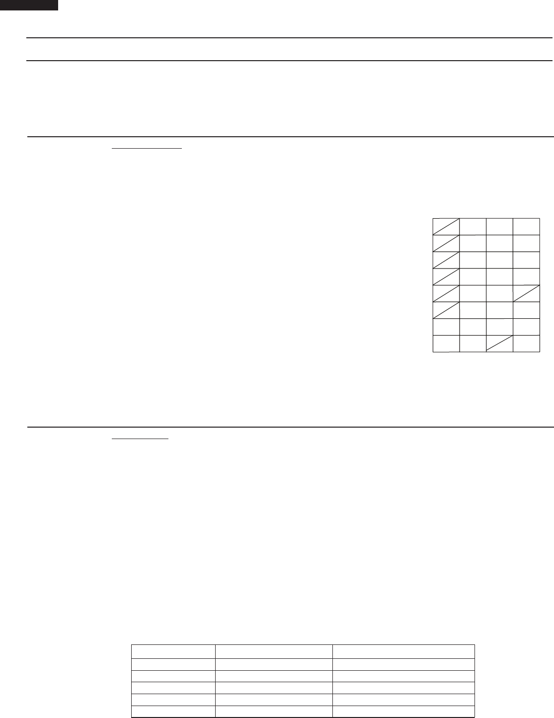
B KEY UNIT TEST
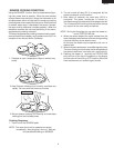
1. Disconnect the power supply cord, and then remove outer case.
1. Disconnect the power supply cord, and then remove outer case.
2. Open the door and block it open.
3. Discharge high voltage capacitor.
4. Disconnect the leads to the primary of the power transformer.
5. Ensure that these leads remain isolated from other components and oven chassis by using insulation
tape.
6. After that procedure, re-connect the power supply cord.
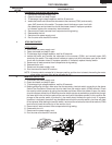
7. Remove the outer case and check voltage between Pin Nos. 5 and 7 of the 4 pin connector (CN-A)
on the power unit with an A.C. voltmeter.
The meter should indicate 120 volts, if not check oven circuit.
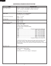
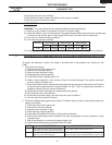
RY1, RY2, RY3 and RY4 Relay Test
These relays are operated by D.C. voltage
Check voltage at the relay coil with a D.C. voltmeter during the microwave cooking operation.
DC. voltage indicated Defective relay.
DC. voltage not indicated Check diode which is connected to the relay coil. If diode is good,
control unit is defective.
RELAY SYMBOL OPERATIONAL VOLTAGE CONNECTED COMPONENTS
RY1 Approx. 26V D.C. Oven lamp / Common
RY2 Approx. 25V D.C. Power transformer
RY3 Approx. 26V D.C. Stirrer motor
RY4 Approx. 26V D.C. Fan motor
RY5 Approx. 26V D.C. Switching regurator for drawer motor
8. Disconnect the power supply cord, and then remove outer case.
9. Open the door and block it open.
10. Discharge high voltage capacitor.
2. Open the drawer and block it open.
3. Discharge high voltage capacitor.
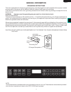
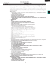
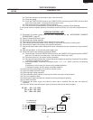
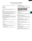
4. If the display fails to clear when the STOP/CLEAR pad is depressed,
first verify the flat ribbon cable is making good contact, verify that
the door sensing switch (stop switch) operates properly; that is the
contacts are closed when the drawer is closed and open when the
drawer is open. If the door sensing switch (stop switch) is good,
disconnect the flat ribbon cable that connects the key unit to the
control unit and make sure the drawer sensing switch is closed
(either close the drawer or short the door sensing switch connecter).
Use the Key unit matrix indicated on the control panel schematic
and place a jumper wire between the pins that correspond to the
STOP/CLEAR pad making momentary contact. If the control unit
responds by clearing with a beep the key unit is faulty and must be
replaced. If the control unit does not respond, it is faulty and must be
replaced. If a specific pad does not respond, the above method may
be used (after clearing the control unit) to determine if the control
unit or key pad is at fault.
5. Reconnect all leads removed from components during testing.
6. Re-install the outer case (cabinet).
7. Reconnect the power supply cord after the outer case is installed.
8. Run the oven and check all functions.
STOP/
CLEAR
REHEAT
6
START/
EASY
MINUTE
1
2
7
SENSOR
COOK
SENSOR
REHEAT
DEFROST
9
8
3
4
OPEN
SENSOR
POPCORN
MICRO
WARM
TIMER
CLOCK
CLOSE
0
5
POWER
LEVEL
SET UP/
HELP
CONTROL
LOCK
ON/OFF