


23
MMD24S
MMD24B
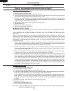
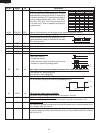
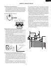
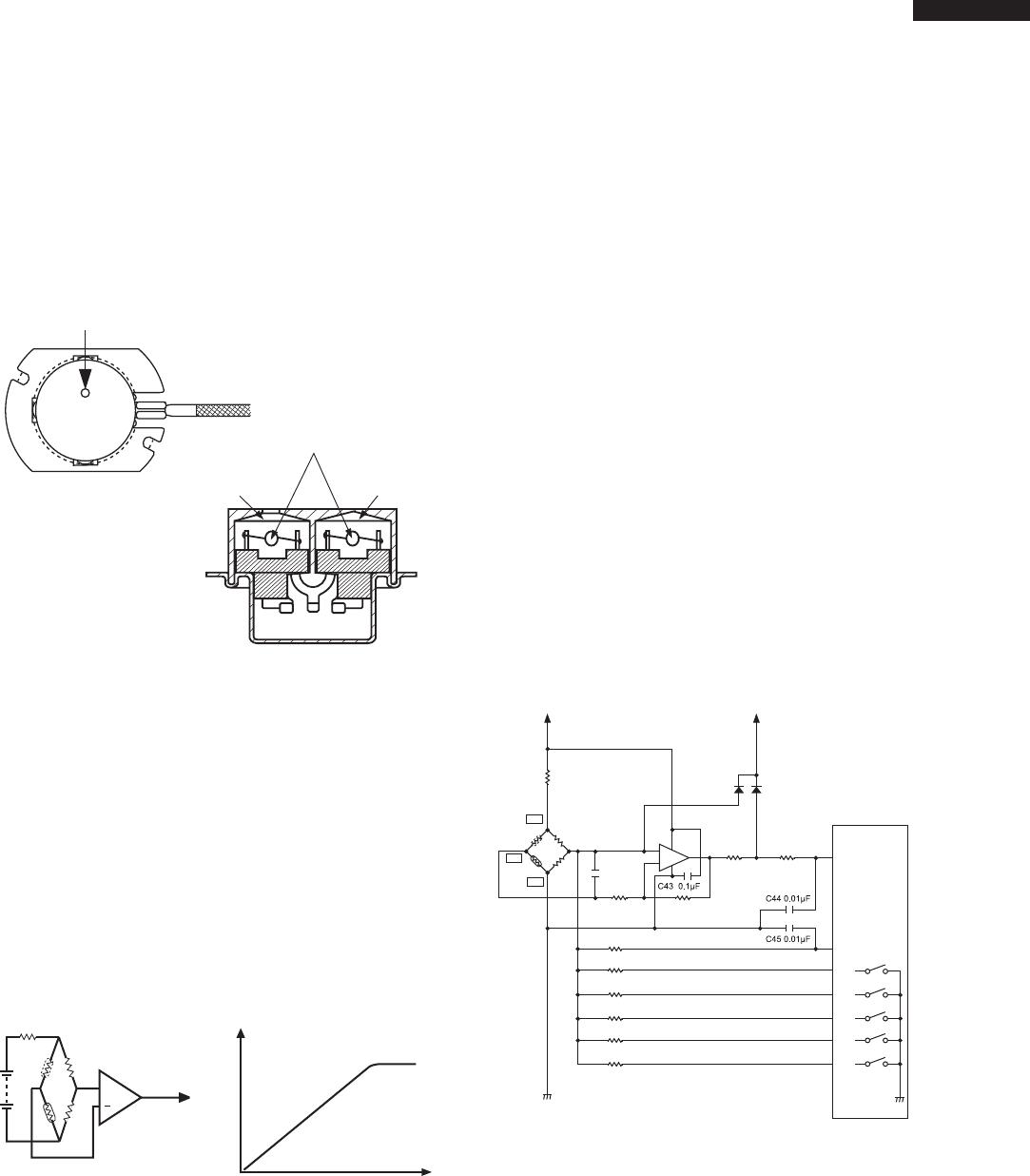
(1) Structure of Humidity Sensor
The humidity sensor includes two thermistors as shown
in the illustration. One thermistor is housed in the closed
vessel filled with dry air while another in the open vessel.
Each sensor is provided with the protective cover made of
metal mesh to be protected from the external airflow.
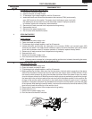
(2) Operational Principle of Humidity Sensor
The figure below shows the basic structure of an
absolute humidity sensor. A bridge circuit is formed by
two thermistors and two resistors (R1 and R2).
The output of the bridge circuit is to be amplified by the
operational amplifier.
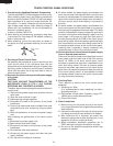
Each thermistor is supplied with a current to keep it heated
at about 150
ο
C (302
ο
F), the resultant heat is dissipated
in the air and if the two thermistors are placed in different
humidity conditions they show different degrees of heat
conductivity leading to a potential difference between
them causing an output voltage from the bridge circuit, the
intensity of which is increased as the absolute humidity
of the air increases. Since the output is varied every
minute, it is amplified by the operational amplifier.
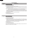
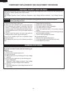
(3) Detector Circuit of Humidity Sensor Circuit
This detector circuit is used to detect the output voltage
of the absolute humidity circuit to allow the LSI to
control sensor cooking of the unit. When the unit is set
in the sensor cooking mode, 16 seconds clearing cycle
occurs than the detector circuit starts to function and
the LSI observes the initial voltage available at its AN6
terminal.
With this voltage given, the switches SW1 to SW5 in
the LSI are turned on in such a way as to change the
resistance values in parallel with R45 ~ R49. Changing
HUMIDITY SENSOR CIRCUIT
the resistance values results in that there is the same
potential at both F-3 terminal of the absolute humidity
sensor and AN6 terminal of the LSI. The voltage of AN7
terminal will indicate about +2.5V. This initial balancing is
set up about 16 seconds after the unit is put in the Sensor
Cooking mode. As the sensor cooking proceeds, the food
is heated to generate moisture by which the resistance
balance of the bridge circuit is deviated to increase the
voltage available at AN6 terminal of the LSI.
Then the LSI observes that voltage at AN7 terminal and
compares it with its initial value, and when the comparison
rate reaches the preset value (fixed for each menu to
be cooked), the LSI causes the unit to stop sensor
cooking; thereafter, the unit goes in the next operation
automatically.
When the LSI starts to detect the initial voltage at AN7
terminal 16 seconds after the unit has been put in the
Sensor Cooking mode, if it is not possible to balance
the bridge circuit due to disconnection of the absolute
humidity sensor, ERROR will appear on the display and
the cooking is stopped.
ventilation opening for sensing
Sensing part
(Open vessel)
Sensing part
(Closed vessel)
Thermistors
S
C
R3
R1
R2
+
Operational
amplifier
Output
voltage
S : Thermistor
open vessel
C : Thermistor
closed vessel
2
Absolute humidity (g/m )
Output voltage
Absolute humidity vs,
output voltage characteristic
R431.8K
VA:+15V VC:+5V
R423.57K
R413.32K
S
C
R5147K
R45620K
R46300K
R47150K
R4875K
R4937.4K
R44360K
R5010K
3
F2
8
4
1
2
IC5
+
-
R40
430
C420.1µF
D40 D41
R5247K
86
63
P04
P03
P02
P01
P00
AN6
SW1
SW2
SW3
SW4
SW5
AN7
LSI
(IC1)
64
52
51
50
49
48
C.Thermistorin
closedvessel
S.Thermistorin
openvessel
F3
F1