


19
MMD24S
MMD24B
TOUCH CONTROL PANEL ASSEMBLY
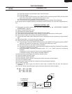
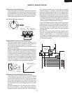
OUTLINE OF TOUCH CONTROL PANEL
The touch control section consists of the following units.
(
1) Key unit
(2) Control Unit
(3) Power unit
The principal functions of these units and the signals com-
municated among them are explained below.
Key unit
The key unit is composed of a matrix, signals generated in
the LSI are sent to the k
ey unit from P10 - P17.
When a key pad is touched, a signal is completed through
the key unit and passed back to the LSI through P20 - P23
to perform the function that was requested.
Control Unit and Power Unit
Control unit consists of LSI, IC, reset circuit, indicator circuit,
power source circuit, relay circuit, buzzer circuit, synchro-
nizing signal circuit, keyboard unit circuit, humidity sensor
circuit and back light circuit.
1)
IC1 (LSI)
This is a microcomputer, responsible for controlling the
entire control unit.
2) IC2
This is the IC to drive the Liquid Crystal Display.
3) IC5
This is the IC to amplify the signal from the humidity
sensor.
4) Reset Circuit
This circuit generates a signal which resets the LSI (IC1)
to the initial state when power is supplied.
5)
Indicator Circuit
A circuit to drive the Liquid Crystal Displays (LCD1).
6)
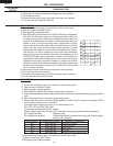
Power Source Circuit
This circuit generates voltages necessary in the control
unit from the AC line voltage.
In addition, the synchronizing signal is available in order
to compose a basic standard time in the clock circuit.
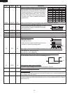
Symbol Voltage Application
VC +5V LSI(IC1)
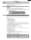
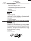
7) Relay Circuit
A circuit to drive the magnetron, fan motor, stirrer motor
and light the oven lamp.
8) Buzzer Circuit
The buzzer is responsive to signals from the LSI to
emit audible sounds (key touch sound and completion
sound).
9) Synchronizing Signal Circuit
The
power source synchronizing signal is available in
order to compose a basic standard time in the clock
circuit.
It accompanies a very small error because it works on
commercial frequency.
10) Door Sensing Switch (Microwave drawer)
A switch to “tell” the LSI if the drawer is open or
closed.
11) Door Position Switch Front / Rear
The switch to “tell” the position of the Microwave drawer
door.
12) Back Light Circuit
A
circuit to drive the back light (Light emitting diodes
LD1- LD3).
13) Humidity Sensor Circuit
This circuit detects moisture of the cooking food to allow
its automatic cooking.
14) Microwave drawer door open-close Circuit
A circuit to drive the microwave drawer door open-close
motor.