


4
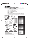
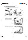
STEP 1: CABINET OR WALL OPENING
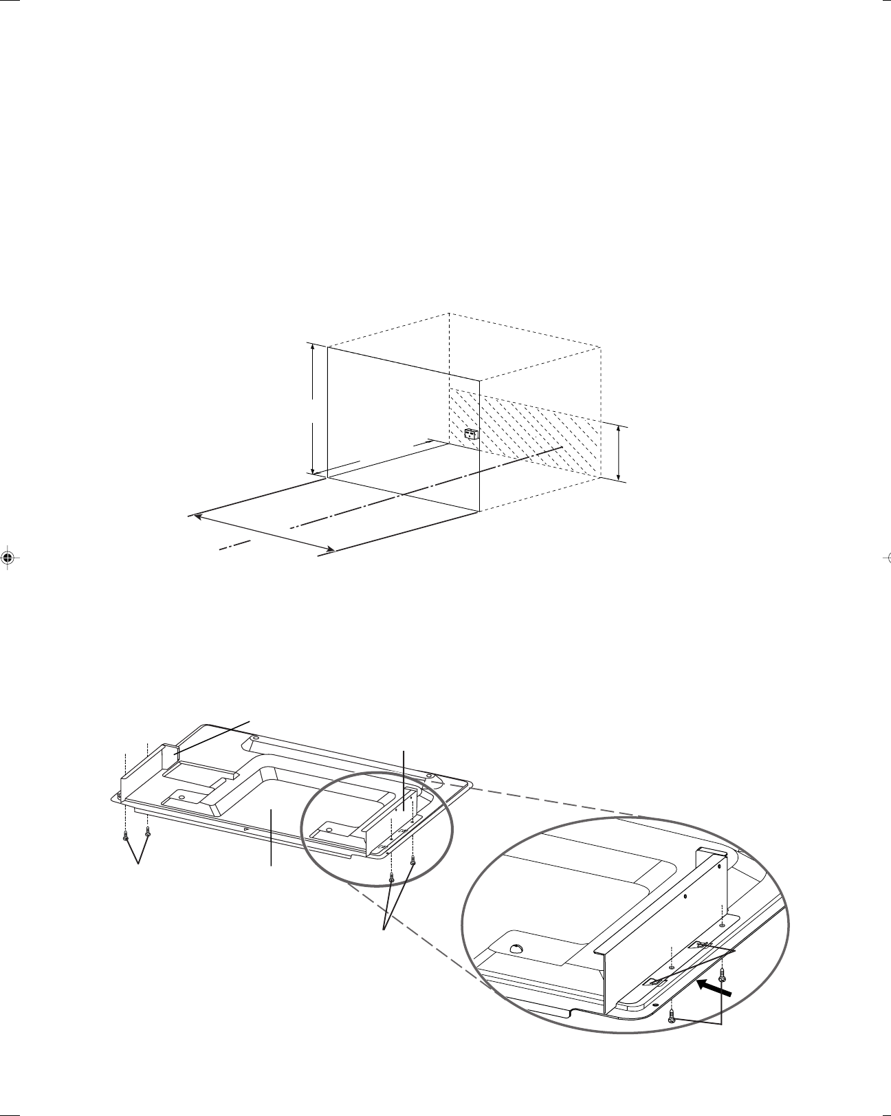
Provide an opening in the wall or cabinet shown in Figure 1.
The depth should be minimum 23
1
/4" (590.5 mm). The floor of the opening should be constructed of
plywood strong enough to support the weight of the oven (about 150 lbs., 68.1 kg) and should be level for
proper operation of the oven.
NOTE: While the proper functioning of the oven does not require that the opening be enclosed (with sides,
ceiling and rear partition), this may be required by local code, and it is suggested that the local code be
checked for any such requirement.
ELECTRICAL SUPPLY
At the rear of the opening, provide a 3 pronged, polarized, electrical outlet, 120 volt A.C., 15 amp. or larger.
This outlet should be located in the shaded area of Figure 1.
It is exceedingly important that the outlet be 120 volts and 15 amps. for optimum oven performance.
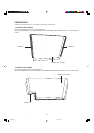
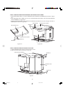
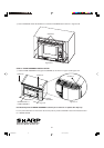
STEP 2: INSTALLATION OF EXHAUST DUCT BOTTOM & DIVIDE PLATE L/R
It is recommended that a sheet of cardboard or other protective material should be placed on the table or
countertop to prevent damage to the surface during assembly.
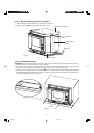
1Place DIVIDE PLATE L/R over 2 caches on EXHAUST DUCT BOTTOM.
2Lock them into EXHAUST DUCT BOTTOM by sliding DIVIDE PLATE L/R in the direction of the
arrow as shown in Figure 2-A.
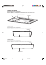
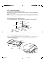
3Tighten 4 SCREWS (A) from the bottom at the left and right sides as shown in Figures 2 and 2-A.
23
1
/
4
(590.5 mm)
"
7
7
/
8
"
(200 m
m)
CL
19" - 19
1
/
8
"
(482 mm - 486 mm)
28" - 28
1
/
4
" (710 mm - 719 mm)
DIVIDE PLATE L
EXHAUST
DUCT BOTTOM
Catches
Figure 1
Figure 2
Figure 2-A
SCREW (A)
DIVIDE PLATE R
SCREW (A)
SCREW (A)
RK12S30 2nd 09.1.14, 11:01 AM4