


8
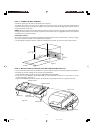
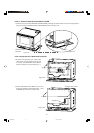
4 Secure EXHAUST DUCT BOTTOM to the shelf with 2 SCREWS (B) as shown in Figures 8-B.
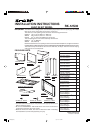
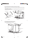
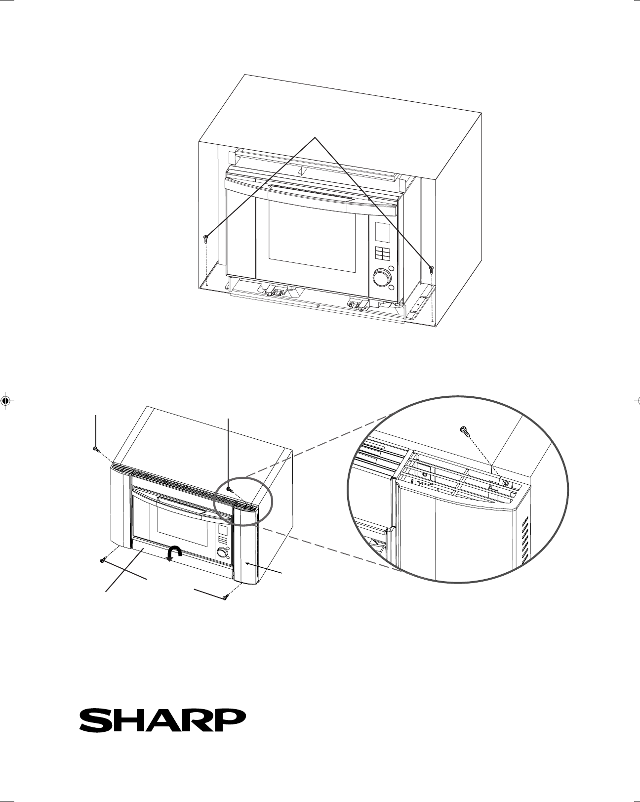
STEP 9: FRAME ASSEMBLY INSTALLATION
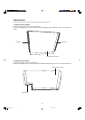
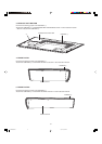
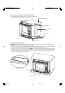
1 Attach FRAME ASSEMBLY and tighten 4 SCREWS (C) as shown in Figure 9 and Figure 9-A.
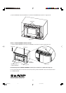
Pull bottom panel of FRAME ASSEMBLY toward you to remove or replace the drip tray.
For any other assistance or information about this product, please call SHARP's Customer Assistance Cen-
ter 1-800-BE-SHARP.
FRAME
ASSEMBLY
Figure 8-B
SCREW (B)
SCREW (C)
SCREW (C)
SCREW (C)
SCREW (C)
Figure 9
Figure 9-A
®
SHARP ELECTRONICS CORPORATION
Sharp Plaza, Mahwah, NJ 07495-1163
BOTTOM PANEL of
FRAME ASSEMBLY
RK12S30 2nd 09.1.7, 5:19 PM8