


HRX-OM-J049-A
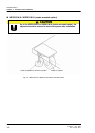
Chapter 3 Transport and Installation
HRG010-W HRG015-W 3.2 Installation
1st edition : Aug. 2006
Rev. A: May. 2007
3-11
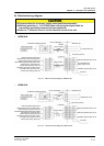
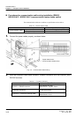
Electrical wiring diagram
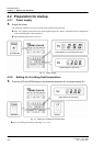
• HRG010-W
z
Fig. 3-9 Electrical Wiring Diagram (HRG010-W)
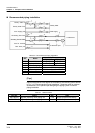
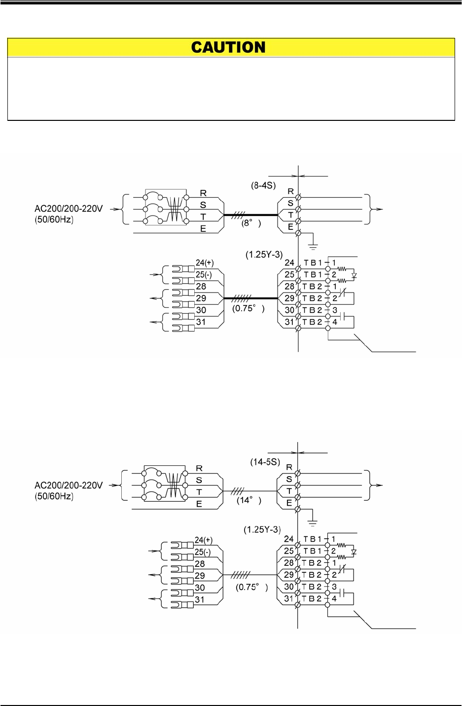
• HRG015-W
Fig. 3-10 Electrical Wiring Diagram (HRG015-W)
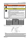
z Prepare cables for the power suppl
y
and signal lines separately .
z Maintain polarities (+, -) of DC24V when connecting the signal cable for
transmitting start/stop command (remote operation).
z Refer to “7.4 Electric Circuit” for the electrical circuit of the unit.
Remote operation signal input
(Remote start upon input of DC+24V)
Remote stop upon input of DC 0V)
Error deteced stop signal output, relay contact
(normally open, closed for error
Contact closed during power-off)
Operation signal output, relay contact
(normally close, opened for error
Contact open during power-off)
Operation signal output circuit
I/O board
Error detected stop
signal output circuit
Remote operation input circuit
FG (Frame ground)
Electrical circuit
Electrical unit
User’s preparation
Power supply
cable
Signal cable
ELB/Current leakage breaker
Power supply input
Operation signal output circuit
I/O board
Remote operation input circuit
Remote operation input circuit
FG (Frame ground)
Electrical circuit
Electrical unit
User’s preparation
Power supply
cable
Signal cable
ELB/Current leakage breaker
Power supply input
Remote operation signal input
(Remote start upon input of DC+24V)
Remote stop upon input of DC 0V)
Error detected stop signal output, relay contact
(normally open, closed for error
Contact closed during Power-off)
Operation signal output, relay contact
(normally close, opened for error
Contact open during power-off)