


Installer Instructions
8
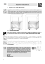
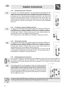
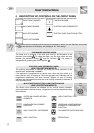
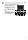
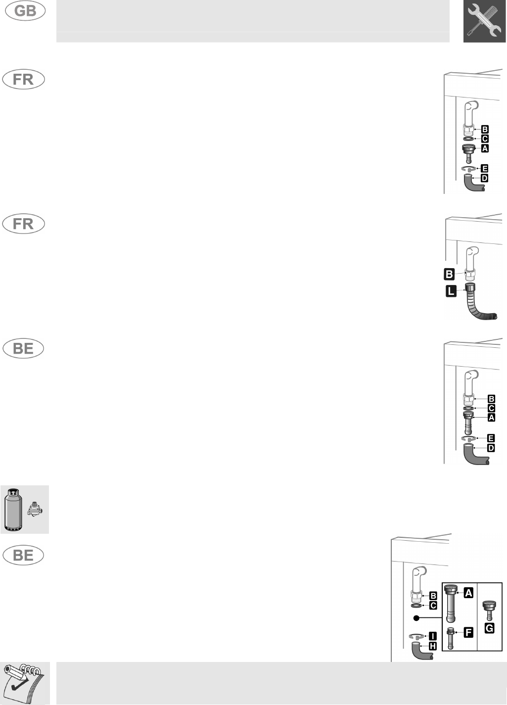
2.4.2 Butane/propane gas connection
For butane, use a pressure regulator on the gas cylinder in accordance with the
regulations in force and a flexible hose in accordance with Standard XPD36-110.
Screw hose-end fitting A onto the end of pipe B of the appliance, interposing seal
C between the two, carefully thread on flexible hose D and fix the hose to the
hose-end fitting using safety collar E. The flexible hose may only be used if the
appliance has been installed in isolation from the network or if the full length of the
hose is visible. For propane, see paragraph “2.4.3 Connection using a collapsible
steel tube”.
2.4.3 Connection using a collapsible steel tube
The gas can be connected using a flexible rubber hose (Standards NFD36-100
and NFD36-103 for methane; Standard XPD36-112 for butane) or using a
collapsible metal tube (Standard NFD36-121 for methane; Standard NFD36-125
for liquid gas). Where a flexible rubber hose is used, please observe the
requirements set out in the paragraph marked "Important".
The connection point on the appliance is a threaded ½” male gas connection.
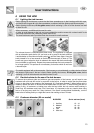
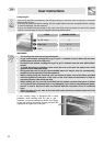
2.4.4 Natural gas connection
The gas can be connected using a flexible rubber hose (Standards NFD36-100
and NFD36-103 for methane; Standard XPD36-112 for butane) or using a
collapsible metal tube (Standard NFD36-121 for methane; Standard NFD36-125
for liquid gas). Where a flexible rubber hose is used, please observe the
requirements set out in the paragraph marked "Important".
Flexible hose/collapsible tube L must be connected directly to the end of pipe B
of the appliance, interposing seal C between the two. The connection point on
the appliance is a threaded ½” male gas connection.
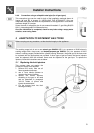
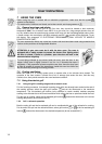
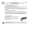
2.4.5 Butane/propane gas connection
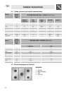
Use a pressure regulator in accordance with the regulations in force and carry out the connection to
the cylinder in accordance with the regulations in force. Make sure that the feed pressure is in
accordance with the values specified in the table in paragraph "3.2/3.3 Tables for burner and injector
characteristics"
Screw hose guide F onto hose guide A; connect the resulting assembly
to gas fitting B (or use hose guide G which must be connected directly to
gas fitting B) and interpose seal C in between the two. Mount the ends of
rubber hose H onto hose guides A+F (or G if appropriate) and the outlet
fitting of the pressure regulator onto the cylinder. Fix the ends of hose H
onto hose guides A+F (or G if appropriate) using bearing I in accordance
with the regulations in force.
Hose-end fittings A-F-G referred to above are not provided with the appliance. Use hose-
end fittings that meet the requirements of the regulations in force only.