Installer Instructions
9
2.4.6 Connection using a collapsible steel pipe (for all gas types)
This connection type can be used for both of the installation methods shown in
figures "A" and "B" in chapter “2. INSTALLING THE APPLIANCE”. Only use
collapsible steel pipes that meet the requirements of the regulations in force with a
maximum length of 2 metres.
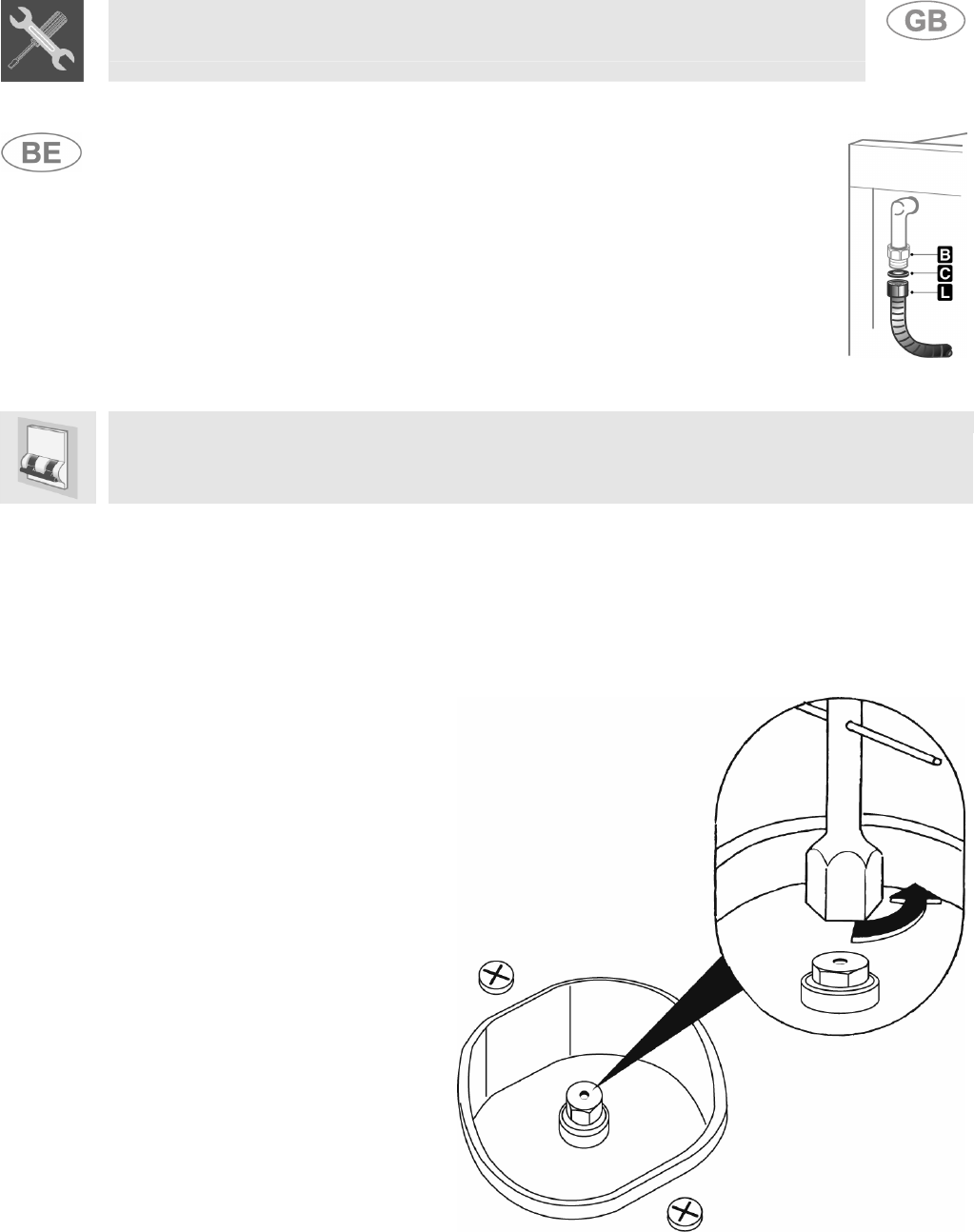
Screw the end of collapsible pipe L onto external threaded ½” gas fitting B (ISO
228-1), interposing seal C in between the two.
Once the installation is completed, check for any leaks using a soapy water
solution, never using flame.
3 ADAPTATION TO DIFFERENT GAS TYPES
Before carrying out any procedure, cut the electrical supply to the appliance.
The cooking range hob is set to use natural gas G20/G25 (2E+) at a pressure of 20/25 mbars in
cooking ranges with a large oven, and butane/propane gas G30/G31 (3+) at a pressure of 28/37
mbars in cooking ranges provided with a cylinder housing. Moreover, the guide eye of the hose must
be replaced with the appropriate one provided. If other types of gas are used, the burner injectors
must be replaced, then the minimum flame must be adjusted on the gas taps. To replace the
injectors, follow the instructions set out below.
3.1 Replacing the hob injectors
This process does not require the
primary air supply to be adjusted.
1. Remove the racks, take out all
flame spreaders and caps;
2. use a 7-mm tubular spanner to
unscrew the burner injectors;
3. replace the burner injectors
according to the gas to be used
and as described in paragraph
“3.2/3.3 Tables of burner and
injector characteristics”.
4. Put the burners back into their
housings correctly.


