


INSTALLATION MODEL 400 RESTAURANT RANGES
PAGE 16 OF 64 OPERATOR’S MANUAL 1182299 REV 3 (05/05) DRAFT
INSTALLATION
Step 4: Connect Electricity (for Models with Convection Ovens)
Wiring diagrams are located on the rear of the range. Be sure that the input voltage and phase match the
requirements shown on the serial plate.
Ranges ordered with a 115V, 60Hz, single-phase electrical rating are factory-supplied with one or two three-
wire cords (one for each oven), each with a three-prong plug that fits any standard three-prong grounded
receptacle. Single-oven units require a 15 ampere supply, while double-oven units require a 20 ampere
supply.
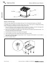
Ranges ordered with a 208/236V, 60Hz, single- or three-phase electrical rating are factory-equipped with
one or two two-pole terminal blocks (one for each oven), located behind cover plate(s) located on the rear of
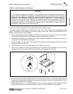
the unit. To connect the supply wires, remove the appropriate cover plate. Route the supply wires and the
grounding wire through the strain relief fitting to the terminal block. Insert the supply wires, one each, into the
two poles of the terminal block and tighten the screws. Insert the ground wire into the grounding lug and
tighten the screw. Re-attach the cover plate.
Three phase units are wired as above, using only two supply wires. The third wire is not used and must be
properly terminated.
All units are shipped wired as specified by factory order. Conversion between single-phase and three-phase
can be accomplished by referring to phase loading and line amperes chart on wiring diagram for wire size
and ampere requirements.
Step 5: Connect Gas Supply
If this equipment is being installed at over 2,000 feet altitude and that information was not specified when
ordered, contact the appropriate authorized Southbend Service Representative or the Southbend Service
Department. Failure to install with proper orifice sizing will result in poor performance and may void the
warranty.
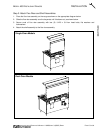
The Serial Plate is located in the compartment below the oven on the right side (on double units - left oven).
It indicates the type of gas the unit is equipped to burn. All Southbend equipment is adjusted at the factory.
Check type of gas on serial plate.
These models are design-certified for operation on natural or propane gases. The unit is shipped configured
for the type of gas specified by the purchaser. A kit for conversion to a different type of gas may be
purchased from Southbend (see page 31 for conversion instructions).
This appliance should be connected ONLY to the type of gas for which it is equipped.
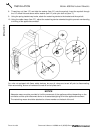
An adequate gas supply is imperative. Undersized or low pressure lines will restrict the volume of gas
required for satisfactory performance. Fluctuations of more than 25% on natural gas or 10% on propane gas
will create problems and affect burner operating characteristics. A 1/8" pressure tap is located on the
manifold to measure the manifold pressure.
An adequate gas supply line to the unit should be no smaller than the I.D. of the pipe from the unit to which it
is connected.
Purge the supply line to clean out dust, dirt, or other foreign matter before connecting the line to the unit.
! CAUTION
ALL PIPE JOINTS AND CONNECTIONS MUST BE TESTED THOROUGHLY FOR GAS LEAKS.
USE ONLY SOAPY WATER FOR TESTING ON ALL GASES. NEVER USE AN OPEN FLAME TO
CHECK FOR GAS LEAKS. ALL CONNECTIONS MUST BE CHECKED FOR LEAKS AFTER THE
UNIT HAS BEEN PUT INTO OPERATION. TEST PRESSURE SHOULD NOT EXCEED 14" W.C.