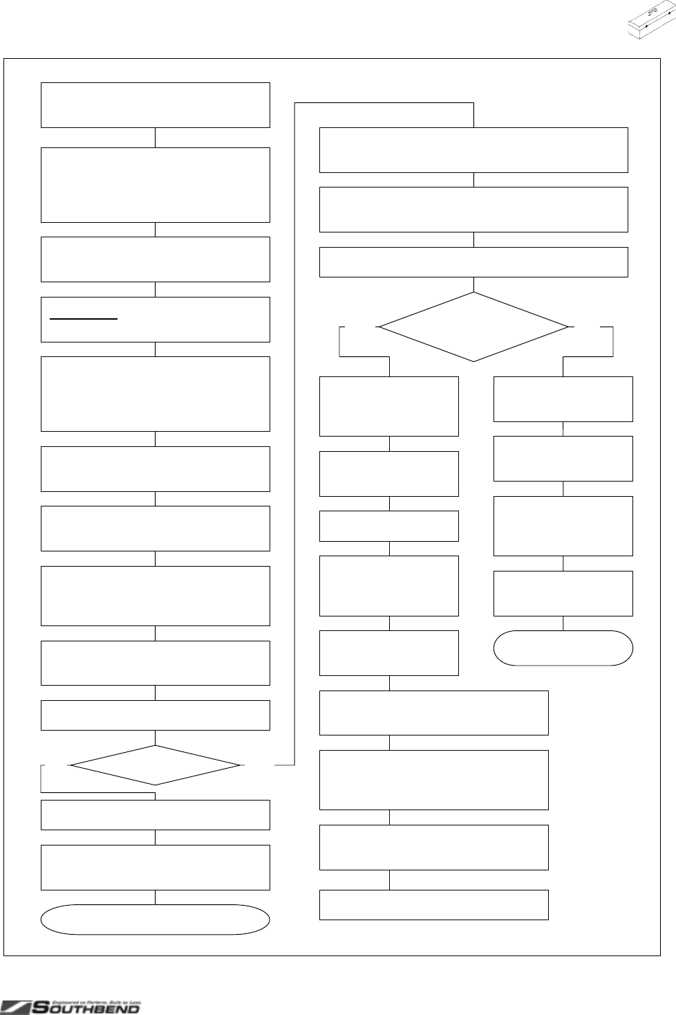
MODEL 400 RESTAURANT RANGES TROUBLESHOOTING
OPERATOR’S MANUAL 1182299 REV 3 (05/05) DRAFT PAGE 41 OF 64
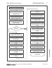
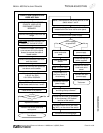
TROUBLESHOOTING
Yes
No
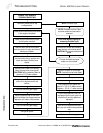
Remove the upper valve panel
cover screws and tilt the panel
forward to expose the back of
blower switch.
CAUTION! WIRING BEHIND THE
PANEL OF THE NEXT STEP.
Remove the control knobs from the
range.
REMOVE THE MAIN POWER
SOURCE. UNPLUG OR
DISCONNECT CIRCUIT
BREAKER.
Check that the wires and terminals
are secure on the switch.
Remove the protective cover from
over the switch.
Place a DVM on the end terminals
of the blower switch wires 1 and 3.
Place switch in on position.
CONVECTION OVEN BLOWER
DOES NOT RUN
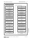
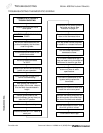
Replace the switch.
Test blower.
Reinstall the switch cover and
valve panel.
Yes No
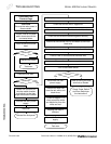
Move a DVM probe to the center terminal of the
switch wires 1 and 2.
Check the voltage specified by the Serial Plate
located behind the oven valve cover panel.
Connect the main power supply.
Is the voltage
as specified?
Reinstall the switch
cover and valve
panel.
Connect the main
power supply.
Check the facility's
power supplies.
Disconnect the main
power supply.
Test oven.
Continues on following page.
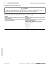
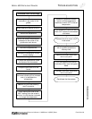
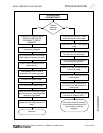
Check that one wire is connected
to the (common), 90° bottom
terminal of the switch.
Disconnect the main
power supply.
Turn on the power
switch.
Open the oven door.
If the blower runs,
the Door Switch is
wired wrong.
Open the kick panel by raising it
and tilting the top outward.
Move the other wire to the lower
leg (N.O.) on the side of the switch.
Reinstall the switch
cover and valve
panel.
Continuit
y
?
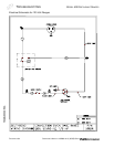
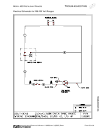
Refer to schematic P/N’s:
1181101 for 120V,
1181102 for 208/240V.


