


I
NSTALLATION
M
ARATHONER
G
OLD
& S
ILVER
S
TAR
G
AS
C
ONVECTION
O
VENS
P
AGE
22 O
PERATOR
’
S
M
ANUAL
1181887
REV
1
INSTALLATION
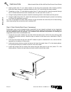
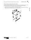
Step 8: Connect Gas Supply
NOTICE
The installation must conform with local codes, or in the absence of local codes, with the National
Fuel Gas Code, ANSI Z223.1, Natural Gas Installation Code, CAN/CGA-B149.1, or the Propane
Installation Code CAN/CGA-B149.2, as applicable, including:
1. The appliance and its individual shutoff valve must be disconnected from the gas supply piping
system during any pressure testing of that system at test pressures in excess of 1/2 psi (3.45
kPa).
2. The appliance must be isolated from the gas supply piping system by closing its individual manual
shutoff valve during any pressure testing of the gas supply piping system at test pressures equal
to or less than 1/2 psi (3.45 kPa).
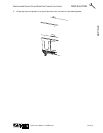
A 3/4" NPT line is provided at the rear for the gas connection.
If this equipment is being installed at over 2,000 feet altitude and that information was not specified when
ordered, contact the appropriate authorized Southbend Service Representative or the Southbend Service
Department. Failure to install with proper orifice sizing will result in poor performance and may void the
warranty.
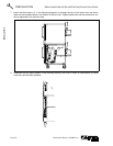
The serial plate is located inside the front lower panel. It indicates the type of gas the unit is equipped to
burn. All Southbend equipment is adjusted at the factory. Check type of gas on serial plate.
These models are design-certified for operation on natural or propane gases. For natural gas, the regulator
is set to deliver a 4.5" W.C. pressure to the manifold. For propane gas, it is set to deliver 11" W.C.
This appliance should be connected ONLY to the type of gas for which it is equipped. The inlet pressure
before the regulator should be 7-10" W.C. for natural gas or 11-14" W.C. for LP gas.
An adequate gas supply is imperative. Undersized or low pressure lines will restrict the volume of gas
required for satisfactory performance. Fluctuations of more than 25% on natural gas or 10% on propane
gas will create problems and affect burner operating characteristics.
An adequate gas supply line to the unit should be no smaller than the I.D. of the pipe from the unit to which
it is connected.
Purge the supply line to clean out dust, dirt, or other foreign matter before connecting the line to the unit.
!
CAUTION
ALL PIPE JOINTS AND CONNECTIONS MUST BE TESTED THOROUGHLY FOR GAS LEAKS.
USE ONLY SOAPY WATER FOR TESTING ON ALL GASES. NEVER USE AN OPEN FLAME TO
CHECK FOR GAS LEAKS. ALL CONNECTIONS MUST BE CHECKED FOR LEAKS AFTER THE
UNIT HAS BEEN PUT INTO OPERATION. TEST PRESSURE SHOULD NOT EXCEED 1/4" W.C.
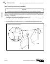
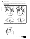
Step 9: Check the Installation
1. Check that all screws and bolts are tightened.
2. Move the oven into the position at which it will be operated.
3. Check that the oven is level. If not, adjust the legs.
4. Check that the appropriate clearances are satisfied (see page 8).