


NOTICE
Southbend reserves the right to change specifications and product design without notice. Such
revisions do not entitle the buyer to corresponding changes, improvements, additions, or replacements
for previously purchased equipment.
NOTICE
These procedures must be followed by qualified personnel or warranty will be void.
GENERAL:
NOTICE
The unit, when installed, must conform with local codes, or in the absence of local codes, with the
National Fuel Gas Code, ANSI 2223.1 -latest edition.
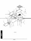
GAS CONNECTION:
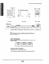
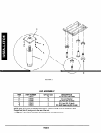
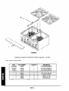
The Serial Plate is located at the rear of the unit on the back panel.
It indicates
the type of gas the unit is equipped to
burn.
All Southbend equipment is adjusted at the factory but may need a finish adjustment once installed.
on serial plate.
These models are design-certified for operation on natural or propane gases.
Check type of gas
This appliance should be connected ONLY to the type of gas for which it is equipped.
Add supply requirement, i.e. pipe size, pressure regulator infomation, operating pressure WC - natural and propane
when all units on line are operating simultaneously.
An adequate gas supply is imperative.
Undersized or low pressure lines will restrict the volume of gas required for sat-
isfactory performance.
Fluctuations of more than 25% on natural gas or 10% on propane gas will create problems and
affect burner operating characteristics. A l/3” pressure tap is located on the manifold to measure the manifold pres-
sure.
An adequate gas supply line to the unit should be no smaller than the I.D. of the pipe from the unit to which it is con-
nected.
Purge the supply line to clean out dust, dirt, or other foreign matter before connecting the line to the unit.
All pipe joints and connections must be tested thoroughly for gas leaks.
Use only soapy water for testing on all gases.
NEVER use an open flame to check for gas leaks. All connections must be checked for leaks after the unit has been
put into operation. Test pressure should not exceed l/4” W.C.
For Natural gas the regulator is set to deliver a 4” W.C. pressure to the manifold.
IO” W.C.
For Propane gas it is set to deliver
A
! CAUflON
This appliance and its individual shutoff valve must be disconnected from the gas supply piping sys-
tem during any pressure testing of that system at test pressures in excess of1/2 PSIG (3.45 KPA).
This appliance must be isolated from the gas supply piping system by closing its individual manual
shutoff valve during any pressure testing of the gas supply piping system at test pressure equal to or
less than 112 PSIG (3.45KPA).
PAGE 3