STRATOSTEAM COUNTERTOP STEAMER INSTALLATION
OWNER’S MANUAL 1185184 PAGE 17 OF 48
STEP 5: ELECTRICAL CONNECTION
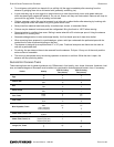
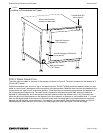
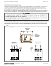
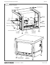
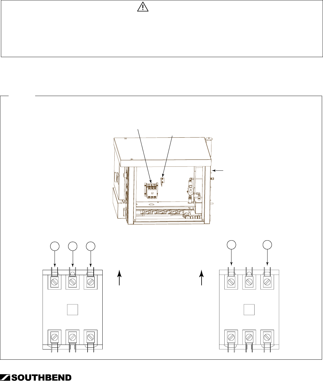
The electric connection is made to the contactor, which is located inside the service compartment on the right side of
the steamer. The right side panel must be removed to gain access to the contactor. A hole on the rear of each
steamer is provided for a 3/4" conduit fitting (solid or flex). An electric cable support bracket and clamp are located
inside of the service compartment, to the right and above the contactor (see Figure 8).
Be sure that the input voltage and number of phases matches the requirement stated on the serial plate. The steamer
is factory wired per customer order. A wiring diagram is attached to the inside of the right side panel of the steamer.
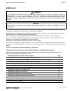
WARNING
A POSITIVE GROUND CONNECTION IS ESSENTIAL. DO NOT ALLOW ANY TAMPERING OR
ADJUSTMENT OF ANY CONTROL OR WIRING. THE STEAMER IS FACTORY SET. ADJUSTING ANY
INTERNAL COMPONENT CAN VOID THE WARRANTY.
THIS STEAMER REQUIRES A KIT TO BE FIELD CONVERTED FROM THREE-PHASE TO SINGLE-PHASE
OR VICE-VERSA. CONSULT FACTORY FOR PHASE CHANGES.
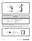
For 3-wire 3-phase installations, connect wires L1, L2, and L3 to the three terminals on the upper end of the contactor.
For 2-wire 1-phase installations, connect wires L1 and L2 to the two outer terminals on the upper end of the contactor.
Make the electrical ground connection to the ground lug located at the top right-hand corner of the contactor bracket.
Figure 9
Electrical Connection
L1 L2 L3
Connections
to Contactor for
3-Phase Models
Top of
Steamer
Contactor
Cable Suppor
t
Bracket
(with clamp)
Hole for
Cable Conduit
(with fitting)
L1 L2
Connections
to Contactor for
1-Phase Models
Top of
Steamer


