


General 4 Information
Installation Instructions
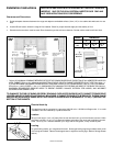
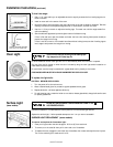
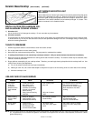
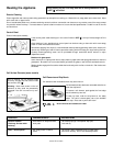
Clearances and Dimensions
a. Provide adequate clearances between the range and adjacent combustible surface (1.3cm (1/2”) to the cabinet side walls and th e rear
wall).
b. Location—Check location where the range will be installed. Check for proper electrical supply and the stability of floor.
c. Dimensions that are shown must be used. Given dimensions provide minimum clearance. Contact surface must be solid and level.
RANGE
A
76.2 cm
30”
78.7 cm
31”
76.2 cm
30”
45.7 cm
(18”)
C
*
76.2 cm (30”)
Minimum
Minimum to
wall on either
side of range.
91.4 cm
(36”)
B
SIDE
VIEW
FRONT
VIEW
A
66 cm (26”)
91.4 ± 0.3 cm
(36 ± 1/8”)
122 cm (48”)
Maximum
114.3 cm (45”)
Door Open
Minimum to
cabinets on
either side of
range.
Maximum depth for
cabinets above
range top.
33 cm
(13”)
BC
30”
DIMENSIONS
1.3 cm
(1/2”)
Electrical Hook-Up
This appliance must be connected to a grounded 120/240 volt or 120/208 volt Range outlet. If no outlet
is available, have one installed by a qualified electrician.
Location
Set your new range 1.3 cm (1/2”) away from the rear wall and line it up with the kitchen counters. Make
sure there is at least 1.3 cm (1/2”) of clearance between each side of the range and the kitchen counters.
Allow 7.6 cm (3”) min. clearance between your range and the refrigerator, if they are side by side.
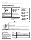
Leveling
For good baking results, your range should be level. Screw type leveling legs are provided at each corner
of the range at the base. Remove the storage drawer to adjust the leveling legs. (Refer to Storage Drawer
section).
* 76.2cm (30”) MINIMUM CLEARANCE BETWEEN THE TOP OF THE COOKING SURFACE AND THE BOTTOM OF AN UNPROTECTED WOOD OR
METAL CABINET; OR 61cm (24”) MINIMUM WHEN BOTTOM OF WOOD OR METAL CABINET IS PROTECTED BY NOT LESS THAN .64cm ( 1/
4”) FLAME RETARDANT MILLBOARD COVERED WITH NOT LESS THAN 0.038cm ( 0.015”) STAINLESS STEEL, 0.061cm ( 0.024”) ALUMINUM
OR 0.051cm ( 0.020”) COPPER. 1.3cm (1/2”) CLEARANCE IS THE MINIMUM FOR THE REAR AND SIDES OF THE RANGE. FOLLOW ALL
DIMENSION REQUIREMENTS PROVIDED ABOVE TO PREVENT PROPERTY DAMAGE, POTENTIAL FIRE HAZARD, AND INCORRECT
COUNTERTOP AND CABINET CUTS.
TO ELIMINATE THE RISK OF BURNS OR FIRE BY REACHING OVER HEATED SURFACE UNITS, CABINET STORAGE SPACE
LOCATED ABOVE THE SURFACE UNITS SHOULD BE AVOIDED. IF CABINET STORAGE IS TO BE PROVIDED, THE RISK CAN BE
REDUCED BY INSTALLING A RANGE HOOD THAT PROJECTS HORIZONTALLY A MINIMUM OF 12.7cm ( 5”) BEYOND THE
BOTTOM OF THE CABINETS.
INSTALLATION AND SERVICE MUST BE PERFORMED BY A QUALIFIED TECHNICIAN.
IMPORTANT: SAVE FOR THE LOCAL ELECTRICAL INSPECTOR’S USE. READ AND
SAVE THESE INSTRUCTIONS FOR FUTURE REFERENCE.