


13
Step 6: Electrical Requirements, Connection & Grounding
• Prior to servicing appliance, always disconnect
appliance electrical supply cord, if so equipped,
from wall receptacle. If appliance is hard-wired to
power supply, disconnect power to unit by turning
off the proper circuit breaker or disconnecting the
proper fuse. Lock service panel to prevent power
from being turned ON accidentally.
• A neutral supply wire must be provided from the
power source (breaker/fuse panel) because criti-
cal range components, including the surface
burner spark reignition module, require 120 VAC
to operate safely and properly. An improper 120/
240 VAC power supply will cause malfunction,
damage this appliance, and possibly create a
condition of shock hazard. If the correct power
supply circuit is not provided, it is the responsibil-
ity and obligation of the installer and user to have
proper power supply connected. This must be
accomplished in accordance with all applicable
local codes and ordinances by a qualified electri-
cian. In the absence of local codes and ordi-
nances, the power supply connection shall be in
accordance with the National Electric Code.
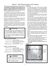
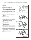
• Observe all governing codes and ordinances
when grounding. In the absence of these codes
or ordinances observe National Electrical Code
ANSI/NFPA No. 70 current issue. See Pages 14
and 15 for grounding method.
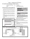
• Electrical wiring diagrams and schematics have
been placed in the toe kick area of the range for
access by a qualified service technician.
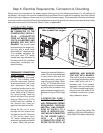
• The DP Dual Fuel Ranges may be connected to
a 240/208 VAC power supply.
Dual Fuel range models can be connected or hard-
wired to the power supply as described on Page 15.
CAUTION
The appliance must be isolated from the gas supply piping system by closing its individual manual shut-
off valve during any pressure testing of the gas supply piping system at test pressures equal to or less
than 1/2 psig (3.5 kPa.).
The appliance and its individual shut off valve must be disconnected from the gas supply piping system
during any pressure testing of the system at test pressures in excess of 1/2 psig (3.5 kPa.).
When checking the manifold gas pressure, the inlet pressure to the regulator should be at least 6" W.C.
(14.9 mb) for natural gas or 11" W.C. (27.4 mb) for propane.
Do not attempt any adjustment of the pressure regulator.
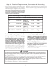
Chart B: Electrical Supply Circuit Requirements
MODELTYPE VOLTAGE CIRCUIT RATING FREQUENCY PHASE
30" 240/208 VAC 35 Amps x2 60 Hz. Single
(35 A each line)
36" 240/208 VAC 35 Amps x2 60 Hz. Single
(35 A each line)
36" with Grill 240/208 VAC 35 Amps x2 60 Hz. Single
(35 A each line)
36" with Griddle 240/208 VAC 35 Amps x2 60 Hz. Single
(35 A each line)