


12
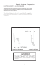
Step 4: Installing Anti-Tip Device
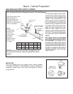
PG30 and PG36 All Gas Ranges (Figures 8A and 8B)
Thermador Service Part No. Qty Description
415078 4 Screw, Phillips, #10 x 1-1/2"
487310 1 Anti-Tip Bracket, Floor-Mounted
IMPORTANT INSTALLATION
INFORMATION:
• The anti-tip bracket may be attached to a solid wood
cabinet having a minimum wall thickness of 3/4".
• The thickness of the wall or floor may require use of
longer screws, available at your local hardware store.
• In all cases, at least two (2) of the bracket mounting
screws must be fastened to solid wood or metal.
• Use appropriate anchors when fastening the mounting
bracket to any material other than hardwood or metal.
• Prepare holes at fastener locations as identified below:
-
For walls, wall studs, or floors composed of solid
wood or metal, drill 1/8" pilot holes.
-
For walls or floors composed of drywall, sheet-
rock or other soft materials, drill 3/16" holes to a
minimum depth of 1-3/4", then tap plastic an-
chors into each of the holes using a hammer.
-
For walls or floors composed of concrete or
concrete block, drill 3/16" holes to a minimum
depth of 1-3/4", then tap concrete anchors into
each of the holes using a hammer.
-
For walls or floors having ceramic tile covering,
drill 3/16" holes through the tile only, then drill into
the material behind the tile as indicated immedi-
ately above.
• If the range is moved to a new location, the Anti-Tip
Device must be removed and reinstalled.
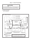
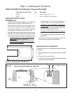
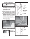
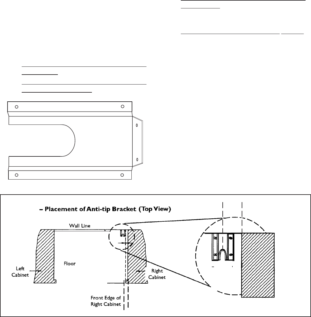
FIG. 8A - Mounting Anti-tip Bracket
MOUNTING ANTI-TIP BRACKET
The alternative floor mounted bracket shall be installed
as follows:
a) Place bracket on floor in position shown in Figure
8B.
b) Secure to floor or wall stud.
c) Later, when the unit is installed,the adjustable leg
will slide under the bracket.
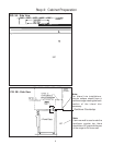
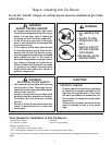
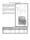
FIG. 8B
2-1/2"
³
³
from edge of range
2-1/2"³
³
(typical -
either side)