


7
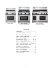
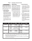
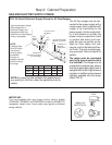
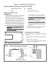
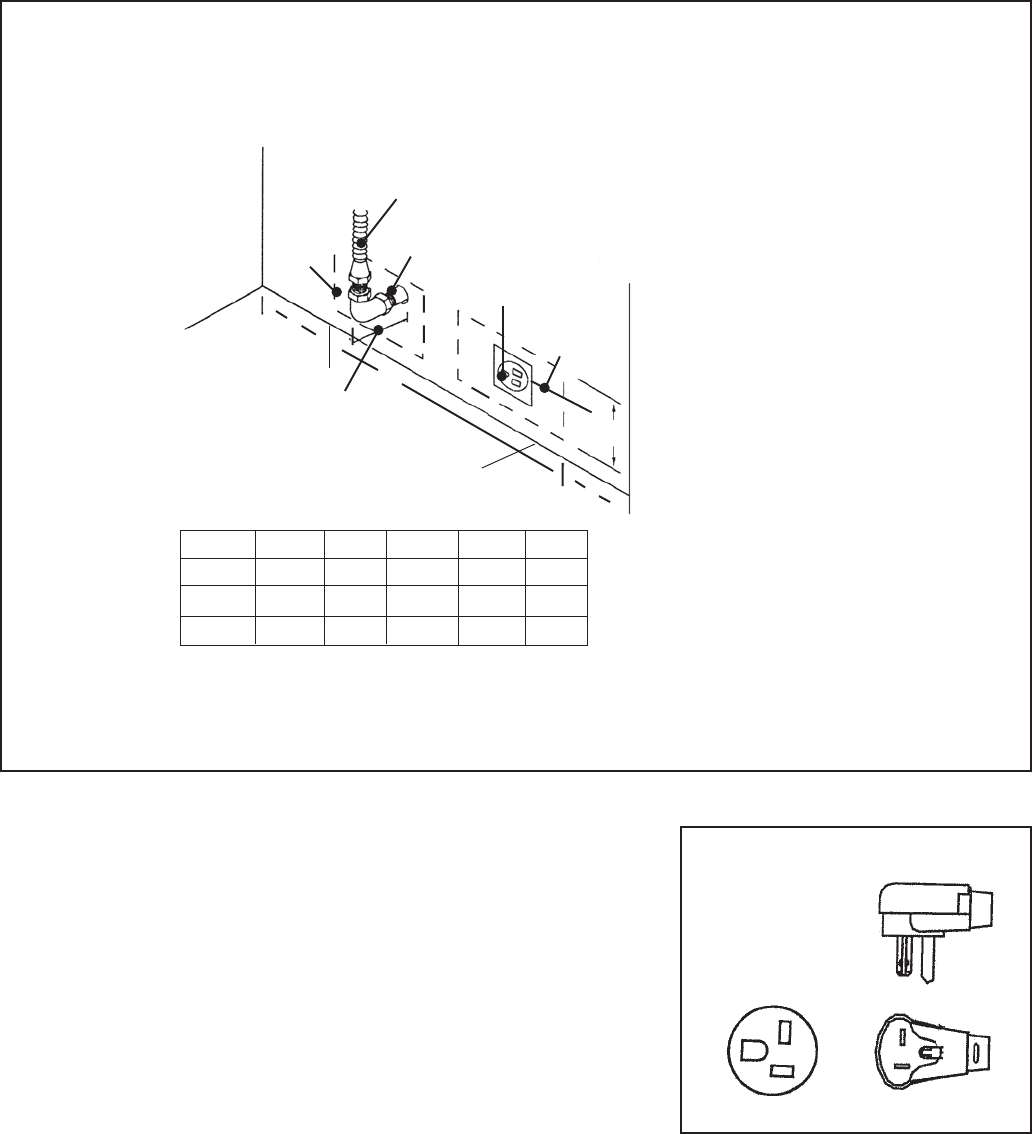
GAS AND ELECTRIC SUPPLY ZONES:
Step 2: Cabinet Preparation
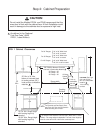
NOTE:
A Manual Gas
Shut-Off Valve
(not shown)
must be easily
accessible
through an
adjacent cabinet
without moving
the range.
Typical placement shown.
Other placement of
Electrical Supply and
Receptacle within the
Electrical and Gas Supply
Zone is acceptable.
FIG. 3A Gas & Electrical Supply Zones for All Gas Ranges
The All Gas ranges may be con-
nected to the power supply with a
range supply cord (supplied with
range) or by hard-wiring to the
power supply. It is the responsibil-
ity of the installer to provide the
proper wiring components (cord
or conduit and wires) and com-
plete the gas connection as dic-
tated by local codes and ordi-
nances, and/or the National Elec-
tric Code. The units must be prop-
erly grounded. Refer to Step 6 for
details.
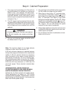
The range must be connected
only to the type of gas for which
it is certified. If the range is to be
connected to propane gas, ensure
that the propane gas supply tank is
equipped with its own high pressure
regulator in addition to the pressure
regulator supplied with the range.
(See STEP 5.)
3/4" Flex Line to
Appliance
B
A
Centerline of
Electrical
Supply Zone
Gas
Supply
Zone
1/2"
N.P.T.
120 VAC Receptacle
(Shown) or Junction
Box
2" Maximum
Protrusion from Wall
for Gas Supply
³
³
³
³
³
³
C
³
³
D
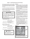
Model A B C D E
PG30 8" 12" 10" 6-1/2" 5-1/4"
PG36 10-1/2" 15" 10-1/2" 6-1/2" 5-1/4"
PG48 16-1/2" 16" 15-1/2" 6-1/2" 5-1/4"
Floor
NOTE: Any opening in the wall behind the appliance and
any opening in the floor under the appliance must be
sealed.
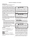
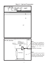
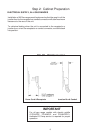
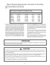
IMPORTANT:
The cord supplied with gas ranges having electric griddle
(PG364GE, PG486GE, and PG484GGE) requires a NEMA 5-20
receptacle, shown here. Local codes may require a different
wiring method.
NEMA 5-20
RECEPTACLE
PLUG
³
³
E