


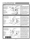
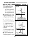
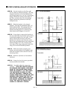
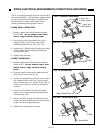
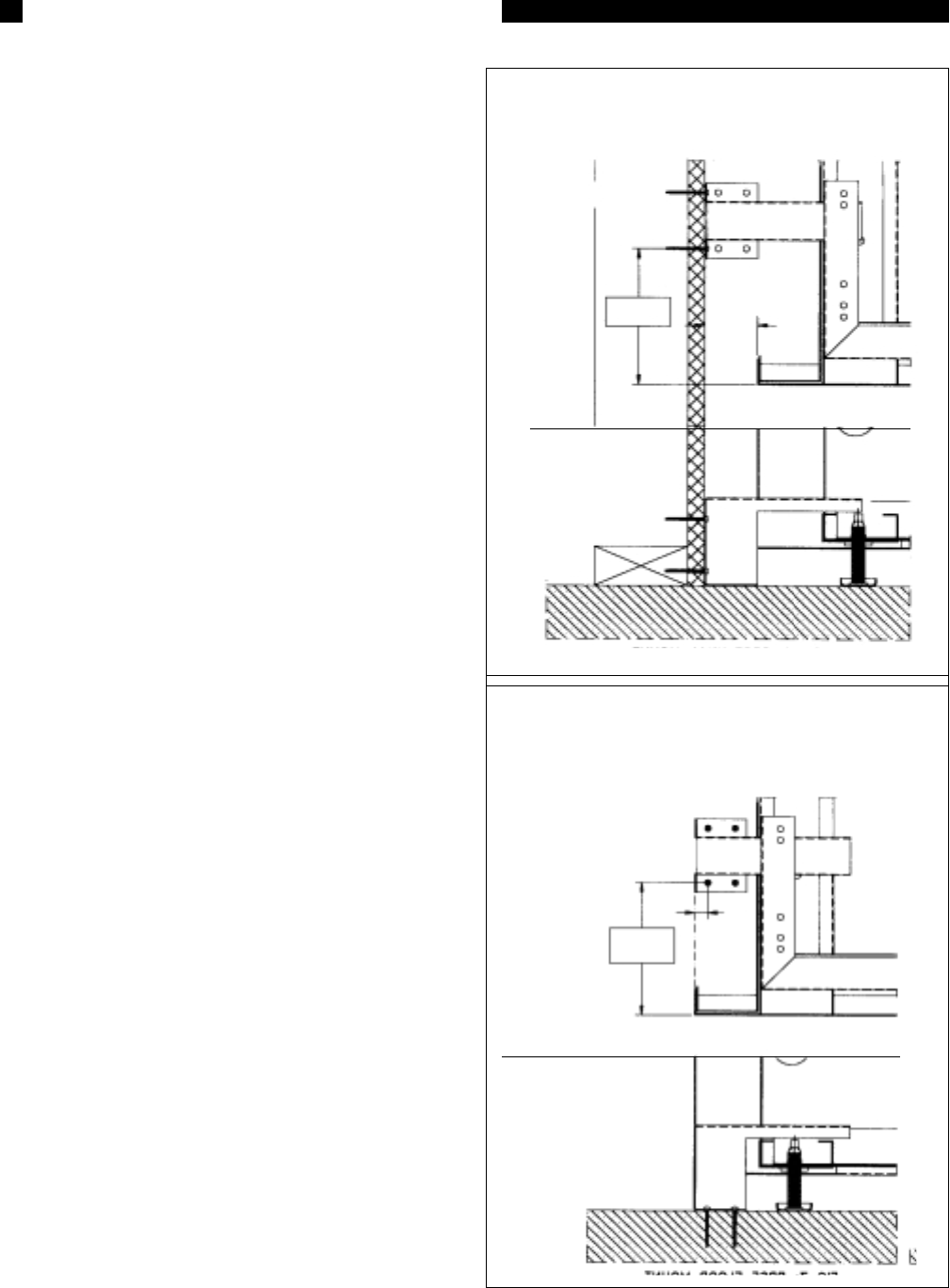
STEP B: Set the bracket on the floor and
turn it
until it is oriented properly. The long
channel should be on the top with the free
end facing towards you,
one set of mounting
flanges should be
resting horizontally on
the floor, and the other set of mount
ing
flanges should be positioned vertically
facing the rear.
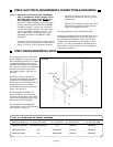
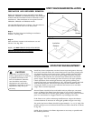
STEP C: Slide the bracket to the desired
position. Note that the minimum (dim. "A")
and maximum (dim. "B") spacing from the
side wall to the center line of the closest
bracket mounting hole is as shown in the
chart above and in Figures 14 and 15.
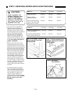
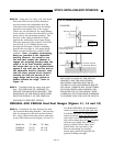
STEP D: If you plan to mount the bracket to
the rear wall, slide the bracket back until it
is positioned against the rear wall. If you
plan to mount the bracket to the floor,
position the bracket such that the center
line of the mounting holes in the horizontal
bracket flanges are 7/16" in front of the
rear edge of the range side panel when the
range is in its final installed position.
STEP E: With the bracket properly posi-
tioned, use the bracket as a template and
mark the location of the selected four (4)
mounting holes.
STEP F: Drill four (4) holes at the marked
locations.
STEP G: Using the four (4) screws provided,
securely fasten the bracket.
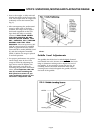
STEP H: Carefully slide the range into
position. FOR THE ANTI-TIP DEVICE
TO ENGAGE THE RANGE, THE REAR
EDGE OF THE RANGE SIDE PANEL
MUST BE WITHIN 2" OF THE VERTI-
CAL MOUNTING FLANGE OF THE
ANTI-TIP BRACKET, REMOVE ANY
LOOSE ITEMS SUCH AS GRATES AND
BURNER CAPS FROM THE TOP OF
THE RANGE, THEN CAREFULLY TILT
THE RANGE FORWARD TO ENSURE
THAT THE ANTI-TIP DEVICE EN-
GAGES TO PREVENT TIPPING.
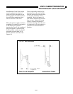
Min. A
Max.B
FIG.15 PRDS Floor Mount
FIG. 14 PRDS Wall Mount
SIDE VIEW
PLAN VIEW
SIDE VIEW
PLAN VIEW
Shown from
Left Side Wall
Shown from
Left Side Wall
716"
Max,
up to 2"
Min. A
Max.B
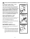
STEP 4: INSTALLING ANTI-TIP DEVICE
Page 14