


STEP 6: ELECTRICAL REQUIREMENTS, CONNECTION & GROUNDING
Dual Fuel models PRDS304, PRDS36 and PRDS48 must be connected to the power supply utilizing one of the
following methods. For all methods of connection, the length of the cord or conduit/wiring must allow the unit to
be slid completely out of the cabinet without having to unplug or disconnect the unit from the power supply.
Recommended minimum free length of cord or conduit is four feet. Electrical installations and grounding must
be in accordance with all local codes and ordinances, and/or the National Electric Code, as applicable.
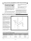
• 3-CONDUCTOR CORD - Where
local codes and ordinances
permit grounding through
neutral, unit may be connected
to the power supply with a 3-
pole, 3-conductor cord kit rated
125/250 volts, 50 amperes, and
marked for use with ranges. The
cord kit must be attached to the
range junction box with a strain
relief which will fit a 1-3/8"
diameter hole. If not already
equipped, the cord must have
#10 closed-loop lugs attached to
the free ends of the individual
conductors, preferably soldered
in place.
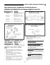
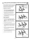
Locate the junction box on the
rear of the unit and remove
cover. Refer to Fig. 16 for
PRDS304 range and Fig. 16a for
PRDS36 and PRDS48 ranges.
Remove the knock out ring in
the junction box to provide a 1-
3/8" diameter hole. Install the
cord to the junction box, and
make the connections to the
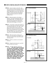
terminal block provided. Refer
to Figures 17 and 17a. The cord
kit must be plugged into a
mating NEMA 10-50R receptacle
provided in the gas and electrical
supply zone, as shown in
Figures 3b, and 3c on Page 6.
•
4-CONDUCTOR CORD - Where
local codes and ordinances DO
NOT PERMIT GROUNDING
THROUGH NEUTRAL, unit
must be connected to the power
supply with a 3-pole, 4-conduc-
tor cord kit rated 125/250 volts,
50 amperes, and marked for use
with ranges. The cord kit must
be attached to the range junc-
tion box with a strain relief
which will fit a 1-3/8" diameter
hole. If not already equipped,
the cord must have #10 closed-
loop lugs attached to the free
ends of the individual conduc-
tors, preferably soldered in place.
Locate the junction box on the
rear of the unit and remove
cover. Refer to Fig. 16 for
PRDS304 range and Fig. 16a for
PRDS36 and PRDS48 ranges.
Remove the knock out ring in the
junction box to provide a 1-3/8"
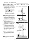
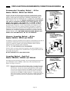
diameter hole. Remove the
ground strap retaining screw and
bend the ground strap up. Refer
to Fig. 18. Install the cord to the
junction box, and make the
connections to the terminal block
provided. Secure the ground
lead from the cord to the junc-
tion box with the screw previ-
ously used to secure the ground
strap. Refer to Fig. 18a. The
cord kit must be plugged into a
mating NEMA 10-50R receptacle
provided in the gas and electrical
supply zone, as shown in Figures
3b, and 3c on Page 6.
• PERMANENT CONNECTION
(HARD WIRING) - Units may be
hard wired to the power supply.
The installer must provide
approved flexible aluminum
conduit, 3/4" trade size, maxi-
mum 6 feet long. Locate the
junction box on the rear of the
unit and remove cover. Refer to
Fig. 16 for PRDS304 range and
Fig. 16a for PRDS36 and
PRDS48 ranges. Remove the
ground strap retaining screw and
bend the ground strap up. Refer
to Fig. 18. The conduit must be
installed to the junction box
using an approved conduit
connector.
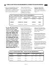
Wiring for the unit is to be
brought into the junction box
through the conduit. Refer to
Chart D on Page 16 for rating of
wiring and sizing of individual
conductors. The ends of the
wiring must have #10 closed-
loop lugs attached, preferably
soldered in place. Make the
connections to the terminal
block provided. Secure the
ground lead to the junction box
with the screw previously used
to secure the ground strap.
Refer to Fig. 18a. The free end
of the conduit must be con-
nected to a junction box pro-
vided in the gas and electrical
supply zone, as shown in
Figures 3b and 3c on Page 6.
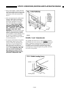
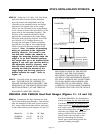
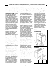
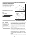
FIG. 16a Location of Junction Box
on PRDS36, 48
Hole for Con-
nection of Cord
or Conduit
FIG. 16 Location of Junction Box
on PRDS304 Range
MODEL DIM “A”
PRDS36 13-1/4"
PRDS48 19"
Page 17