


STEP
4:
INSTALLING
ANTI-TIP
DEVICE
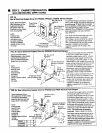
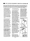
STEP
H:
Using
the
l/4"-20
x
1/2"
Hex
Head
Bolt,
Hex
Nut
and
two
(2)
Flat
Washers,
securely
attach
the
Adjustable
Anti-Tip
Channel
to
the
existing
hole
in
the
flange
located
at
the
bottom
rear
of
the
range.
(There are
two
(2)
holes
in
the
range
flange,
so be
certain
to
select
the
hole
that
is
on
the
same
side
as
the
mounting
bracket.)
The
flat
face
of
the
channel
should
be
flush
against
the
underside
of
the
range
flange.
From
the
bottom
of
the
channel,
screw
the
two
(2)
#10
x
1/2"
Phillips
Screws
up
through
the
first
pair
of
holes
extending
beyond
the
rear
edge
of
the
range
flange.
These
screws
will
prevent
rotation
of
the
channel.
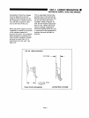
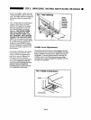
Note:
A
number
of
mounting
holes
are
provided
in
the
Adjustable
Anti-Tip
Channel.
Be
certain
to
use
the
hole that
enables
the
channel
to
engage
the
mounting
bracket
when
the
range
is
in
its
final
installed
position.
For
ranges
that
are
to
be
installed
flush
against
a
rear
wall,
use
the
first
hole
in
the
Adjustable
Anti-Tip
Channel,
such
that
the
short
portion
of
the
channel
extends
out
from
the
bottom
of
the
range
flange
and
the
long
portion
is
hidden
beneath
the
range.
Refer
to
Figure
10.
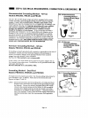
STEP
I:
Carefully
slide
the
range
into
position.
FOR
THE
ANTI-TIP
CHANNEL
TO
ENGAGE
THE
MOUNTING
BRACKET,
THE
REAR
EDGE
OF
THE
RANGE
SIDE
PANEL
MUST
BE
WITHIN
2"
OF
THE
VERTICAL
MOUNT
ING
FLANGE
OF
THE
ANTI-TIP
BRACKET,
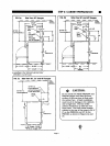
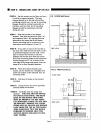
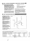
FIG.
13
PRG36
Floor
Mount
PLAN
VIEW
Anti-Tip
Channel
O O
O
O'
*—
Mounting
Bracket
"T
PRG304:
2-3/4"
PRG36:
4-5/8"
±
May
Be
Used
On
Either Left
or
Right
Side
(Right
Shown)
SIDE
VIEW
Leveling
Leg
-
-Anti-Tip
Channel
-
Mounting
Bracket
AND
THE
ADJUSTABLE
MOUNTING
CHAN
NEL
MUST
BE
ATTACHED
TO
THE
APPRO
PRIATE
MOUNTING
HOLE.
REMOVE
ANY
LOOSE
ITEMS
SUCH
AS
GRATES
AND
BURNER
CAPS
FROM
THE
TOP
OF
THE
RANGE,
THEN
CAREFULLY
TILT
THE
RANGE
FORWARD
TO
ENSURE
THAT
THE
ANTI-TIP
DEVICE
ENGAGES
TO
PREVENT
TIPPING.
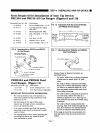
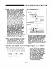
PRDS304
AND
PRDS36
Dual-Fuel
Ranges
(Figures
11,
14
and
15)
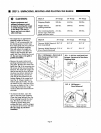
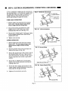
STEP
A:
Determine
the
best
location
for
Anti-
Tip
Channel
Mounting
Bracket.
The
bracket
may
be
mounted
to
the
wall or
floor
behind
the
range,
offset
from
side wall
as
indicated
in
the
chart
below
and
in
Figures
14
and
15:
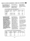
Model
No.
PRDS304
PRDS36
"A",
Min.
5-1/2"
6-1/2"
"B",
Max.
16-1/2"
13-1/2"
For
Model
PRDS304,
the
dimensions
shown
are
from
the
left
side
wall
only.
For
Model
PRDS36,
the
dimensions
shown
are
from
either
the
left
or
right
side
wall.
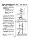
Locate
the
bracket
on
the
side
of
the
range
that
will
not
interfere
with
the
gas
supply
line,
electrical
wiring,
conduit
or
any
other
item.
Select
either
the
rear
wall
or
the
floor
for
mounting
the
bracket,
based
upon
which
will
provide
the
greatest
holding
strength.
Page
13