17
FIN-PRC003-EN
Mechanical
Specifications
Model EWFB
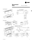
Control Sections:
•
6" (152 mm) long control section for
factory mounting of 1 or 2 controls.
Right or left side mounting are
available with right side being
standard. Requires one foot (0.3048 M)
of extended enclosure for installation.
Control sections are field wired to the
heater.
•
12" (305 mm) long control section for
factory mounting of 1, 2 or 3 controls.
Right or left side mounting are
available with right side being
standard. Requires one foot (0.3048 M)
of extended enclosure for installation.
Control sections are field wired to the
heater.
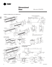
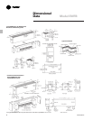
Accessories: Accessories are approved
as 40 ampere wireways and are of the
same material and compatible design
as the heater section.
•
Inside corners 90 - 180 degrees.
•
Outside corners 180 - 270 degrees.
•
End caps left or right hand.
•
2" (51 mm) and 6" (152 mm) wall trims.
•
1
1
/2" (38 mm) splice plates.
•
1
/4" (6.4 mm) wire mesh factory
installed under outlet grille on
enclosure and blank enclosure sections
and extended enclosure sections.
•
Pedestals – Pedestal brackets are
available for floor mounting in lobbies
and in front of windows for all models
except ASHDB 10" (254 mm), 12" (305
mm), 14" (356 mm), 18" (457 mm) and
20" (508 mm) high heaters. Factory
installed to the bottom of the unit for
field furnished power wiring to be run
through the center of the pedestal into
the bottom of the units junction box for
connection to the heater.
The knockouts that are provided in the
side and rear of each heaters junction
box and the back panel mounting
holes for wall mounting of units are
not furnished when pedestals are
ordered.
2' to 6' (0.6 to 1.83 M) heaters require
two pedestals, 6' to 8' (1.83 to 2.44 M)
heaters require three pedestals,
9' (2.74 M) and 10' (3.05 M) heaters
require four pedestals.
•
Finished Back Panels – Finished back
panels either painted or anodized in
the same color as the heater are
available for pedestal floor mounted
heaters to be installed in front of
windows and in lobbies.
•
Blank enclosure sections manufactured
of solid metal grilles and are
independent pieces of enclosure not
joined to the heater and are fully
enclosed to allow branch circuit wiring.
Available in 1 foot (0.3048 M) through
10 foot (3.048 M) lengths in 1 foot
(0.3048 M) increments. Can be
modified for use with hydronic heating
elements for models DBT, DBF, DBCT,
DBCF and ASHDB only.
•
Color Finish Options
- Clear Anodized
- Bronze Anodized
- Black Anodized
- Beige Baked Enamel* 2-7-2894
- White Baked Enamel* 2-1-5098
- Brown Baked Enamel* 2-7-3894
- Black Baked Enamel* 2-6-5054
*Colors per Electric Wall Fin Color
Selection Chart FIN-S-3.
•
Anodized colors available for all
models except Model ASHDB.
Hydronic Heating Units
Blank enclosure sections for use with
hydronic heating elements are modified
to have the air outlet grille and bottom
air inlet or bottom front air inlet grille in
the same configuration as listed above
for each model electric heater.
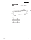
Maximum Element Fin Size per Model
Model Maximum Fin Size
DBT & 2
3
/4" x 4" and 3
1
/4" x 3
1
/4"
DBCT 70 mm x 102 mm and 83 mm x 83 mm
DBF & 2
3
/4" x 4" and 2
3
/4" x 3"
DBCF 70 mm x 102 mm and 70 mm x 76 mm
ASHDB 4
1
/4" x 4
1
/4"
108 mm x 108 mm
Note:
3
1
/4" (83 mm) x 5
1
/4" (133 mm) fin size and
2
3
/4" (70 mm) x 5" (127 mm) fin size cannot be used with
these size enclosures.


