26 RLC-SVD03A-EN
Current Transformer
essary to remove a cap over the top of the connector to gain access to
the connector conductors.)
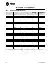
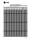
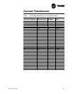
6. Refer to Table 7 which lists the normal resistance range for each exten-
sion of current transformer. Check the measured resistance against the
value listed per transformer extension. If the resistance is within toler-
ance, the transformer and MTA can be considered good. Go on to step 8.
7. If the resistance reading above is out of tolerance, the problem is either
with the transformer, its wiring, or the MTA connector. First double check
the schematic to be sure you are working the proper lead pair. Then cut
the leads to the particular transformer near the MTA connector and
repeat the resistance measurement by stripping insulation from the
wire's end. Once the fault has been isolated in this manner, reconnect
leads or install a new transformer or connector.
More than one current transformer is terminated to a single MTA. When
replacing, take care to note the proper positions of the respective trans-
former wire terminations on the MTA for the re-termination. The current
transformers are NOT polarity or directionally sensitive. The transformer
lead wiring is #22 AWG, UL 1015 600V and the proper MTA connector
(red color code) must be used to ensure a reliable connection. If the fault
can be isolated to the current transformer or its wiring apart from the con-
nector, the connector can be reused by cutting off the bad transformer
and splicing in a new transformer using wire nuts.
8. If the transformer/connector resistance proves accurate, recheck the
resistance with the connector held at different angles and with a light
lead pull (less than 5 lb.) to test for an intermittent condition.
9. To perform the following test, you will need to use a digital voltmeter with
a diode test function,. With the transformer MTA disconnected and the
power off to the MCSP, perform a diode test across the corresponding
pair of current transformer input pins on the MCSP (header J5). The
meter should read from 1.0 to 1.5 volts for each current transformer input.
Repeat using the opposite polarity. The same reading should result.
Extreme errors suggest a defective MCSP module. If the diode voltage
drops prove accurate, reconnect the transformers to the MCSP and
repower the unit.
10. With the CT's reconnected to the MCSP, attempt a restart of the chiller.
As the given compressor is started, and the inrush locked rotor transient
has passed, (locked rotor transient should last less than one second)
simultaneously monitor the actual compressor phase current(s) (using a
clamp-on type ammeter) and the voltage developed at the respective cur-
rent transformer's termination at the MCSP (using a digital volt-meter on
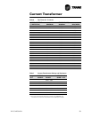
a 0-20 VAC scale). Refer to Table 8 for the compressor phase current to
output voltage relationship for each extension current transformer. Using
Table 8, look up to current that corresponds to the output voltage read by
the voltmeter and compare to ammeter reading. Assuming relatively
accurate meters, the values should agree to within 5%.
11. If the measured current and the output voltage from the CT agree within
the tolerance specified, the CT is good. If diagnostics, overload trips, or
other problems potentially involving current sensing continue to occur


