48 RLC-SVD03A-EN
Module Power and Miscellaneous I/O
I/O terminals
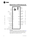
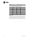
For the checkout of the I/O, refer to the block diagram of the module in Figure
10 and the Chiller Wiring Diagrams for both high and low voltage circuits. All
voltages are measured differentially between terminal pairs specified unless
otherwise indicated. The first terminal in the pair is the positive (or hot)
terminal. Voltages given are nominals and may vary by ±5%. Unregulated
Voltages (unreg) or 115 VAC voltages may vary by ±15%.
° TP1 + 5V
° TP2 +12V
J5-1 — 115V H
J5-2 — 115V H
J5-3 — KEY (N/C)
IPC (+) —
J1-4 J5-4 — 115V N
IPC (-) —
J1-3 J5-5 — 115V N
IPC (+) —
J1-2
IPC (-) —
J1-1
TB3-1 — CHILLED
H
MANUF. NO
J2-2 WATER FLOW
I
USE ONLY NO
J2-1 TB3-2 — SWITCH
G
H
OUTDOOR AIR —
TB1-1
TEMP —
TB1-2 TB3-3 — EXTERNAL
V
AUTO/STOP
0
EMERGENCY —
TB1-3 TB3-4 — INPUT
L
STOP —
TB1-4
T
L A
0
NNS —
TB1-5 TB4-1 — COM ALARM
G
W
NNS —
TB1-6 TB4-2 — (NO) RELAY
E
TB4-3 — (NC)
V
NOT USED
{
CEWT —
TB2-1
I
0
CEWT —
TB2-2
N
L
TB4-4 — COM COMPR
P
T
NOT USED
{
CLWT —
TB2-3 TB4-5 — (NO) RUN
U
A
CLWT —
TB2-4 RELAY
T
G S
E
EVAP ENTERING —
J3-5
WATER TEMP —
J3-4 TB4-6 — COM MAX CAPACITY
0
I
TB4-7 — (NO) RELAY
U
N
KEY J3-3
T
P
TB4-8 — COM EVAP PUMP
P
U
EVAP LEAVING —
J3-2 TB4-9 — (NO) RELAY
U
T
WATER TEMP —
J3-1
T
S
TB4-10 — COM SPARE
S
AUX TEMP —
J6-3 TB4-11 — (NO) RELAY
KEY (N/C) J6-2
AUX TEMP —
J6-1
U/O VOLT TRANSF —
J4-3
KEY J4-2
U/O VOLT TRANSF —
J 4-1
Figure 10 CPM (Chiller) Module (1U1)


