


80 RLC-SVD03A-EN
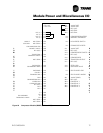
Variable Speed Fan System
The purpose of this troubleshooting guide is to help technicians determine if
the variable speed fan inverter, the compressor module, the variable speed
fan inverter contactor, the fan motor or the interconnecting wiring is faulty.
ƽ WARNING
Hazardous Voltage w/Capacitors!
Disconnect all electric power, including remote disconnects
before servicing. Follow proper lockout/tagout procedures to
ensure the power cannot be inadvertently energized. For variable
frequency drives or other energy storing components provided by
Trane or others, refer to the appropriate manufacturer’s literature
for allowable waiting periods for discharge of capacitors. Verify
with an appropriate voltmeter that all capacitors have discharged.
Failure to disconnect power and discharge capacitors before
servicing could result in death or serious injury.
Note: For additional information regarding the safe discharge of
capacitors, see PROD-SVB06A-EN or PROD-SVB06A-FR
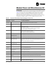
In this troubleshooting procedure, the components will be referred to by the
descriptions below:
Inverter Diagnostics
The Inverter has two LED’s for diagnostic purposes. They are:
Power On LED: This green LED is illuminated any time that more than 50
VDC is present on the DC Bus Capacitors. Typically when power is removed
from the TRANE AC INVERTER this LED will remain illuminated for up to 60
seconds while the DC Bus Capacitor Voltage discharges. This LED also
indicates that the 5 VDC Supply Voltage on the TRANE AC INVERTER control
board is present.
Alarm LED: When this red LED is illuminated constantly, it indicates that the
motor is overloaded and the drive is about to fault on a motor overload. When
the Alarm LED is flashing, it indicates the drive is faulted. By counting the
number of times the Alarm LED flashes, the cause of the fault can be deter-
mined. The following table lists the possible fault conditions for the TRANE
AC INVERTERS and the number of times the Alarm LED will flash:
Fault Condition Number of Alarm LED flashes
Bus Overcurrent Fault 1
Description Circuit 1 Circuit 2
Compressor Module 1U4 1U5
Variable Speed Fan Motor 3B2 4B2
Variable Speed Fan Inverter 6U9 6U10
Variable Speed Fan Inverter Contactor 1K9 1K13
Variable Speed Fan Inverter Fuses 1F18 - 1F20 1F21 - 1F23