RLC-SVD03A-EN 83
Variable Speed Fan System
.6 VDC. If there is no voltage at either of these two test points, check the
incoming 115 VAC between pins J6-1 (hot) and J6-5 (neutral) and check
fuse F1, mounted on the upper right-hand corner of the circuit board. If
the fuse is OK and the voltage between J6-1 and J6-5 is 115 VDC, but the
TP1 and TP2 voltages are out of range, replace the compressor module.
7. Remove connector P9 or P10 (whichever applies) from the inverter and
place a jumper wire between terminals F and FR on the female connec-
tor. See Figure 11-1 for the location of these wires. This will prevent the
control from reporting a fault diagnostic. Restart the unit and carefully
measure the DC voltage between wires C (+) and CR ( - ) on the same
female connector. The voltage should be 2 to 10 VDC when the compres-
sor on the affected circuit is running. At compressor start, this voltage
will start at approximately 2 VDC and gradually ramp up to about 10 VDC.
This voltage level is directly proportional to fan speed. At 5 VDC, the fan
should be running at 50% of full speed and at 7 VDC the fan should be
running at 70% of full speed.
NOTE: The output from the compressor module is a pulse width modulated
signal, 10 volt peak and 10 Hz. fundamental. It's average value can be read
with a DC voltmeter.
8. Remove the jumper wire and reconnect connector P9 or P10. While the
inverter is still powered, measure the DC voltage between pins J9-4 (+)
and J9-3 ( - ) on the compressor module. The connector must be plugged
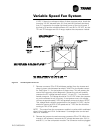
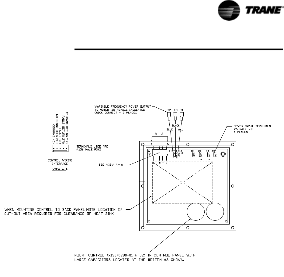
Figure 25 Variable Speed Fan Inverter


