RLC-SVD03A-EN 27
Current Transformer
with all phase currents to the compressors verified to be within their nor-
mal range, then the problem is either with the CT selection, MCSP Com-
pressor Overload Dip Switch Setting, or the MCSP's current input, analog
to digital (A/D), or dip switch input circuitry. Since the first two items
were verified in Step 2 using Table 5, that leaves only the MCSP circuitry
as an issue. It is advisable to replace the MCSP module at this point.
However if verification of the MCSP Current sensing operation is desired,
go to step 12 below.
12. There are two ways that the MCSP's current sensing can be checked.
Both methods use the CLD display of the %RLA from each MCSP (Com-
pressor Report) for indication of the sensed current. The first is straight-
forward equation and assumes that the proper Compressor Overload dip
switch setting and current transformer have been selected:
%RLA =
To check the displayed % RLA as a function of the output voltage from the
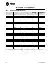
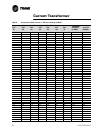
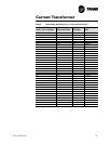
current transformers (as connected at the MCSP), Tables 8 and 9 are utilized.
In Table 8 look up (or interpolate) the “% of CT rating” corresponding to the
maximum of the three CT Input Voltages (VAC rms) as read at the MCSP. (The
table is necessary because the voltage developed at the MCSP is not linear
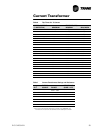
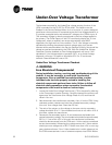
with the CT's secondary current). Next, check the Compressor Current
Overload setting of switch SW2 on the MCSP and find the corresponding
“SOFTWARE GAIN” in Table 9. The % RLA displayed by the CPM should be:
%RLA = % CT Rating X SOFTWARE GAIN
The preceding equations should only be applied during steady state current
draws (after transition). Inrush transient currents and associated CT output
voltages can be expected to be from 3 to 6 times the steady state values, and
the displayed value only reads up to 255% RLA. The accuracy of the
displayed value should be within ± 5% of that predicted using the Input
voltage. However, the end to end accuracy of the displayed value compared
to the actual %RLA max. phase current is ± 3.3% over the range of 50 to
150% of CT rating.
13. If no phase currents are measured with the amprobe on any or all of the
legs to a given compressor immediately following the attempted staging
of that compressor by the MCSP, the problem lies either with the
contactor, motor circuit or the MCSP relay outputs. Refer to MCSP
Checkout Procedure in Compressor Module (MCSP) (1U4 AND 1U5) on
page 72.
Measured Compr. amps of max. phase
Nameplate Compressor RLA
------------------------------------------------------------------------------------------------------- -


