RLC-SVD03A-EN 23
Current Transformer
Each compressor motor has all three of its line currents monitored by torroid
(doughnut) current transformers. While the MCSP utilizes all three of the
signals, it only displays the maximum phase at any given time. These currents
are normalized with respect to the Rated Load Amps of the respective
compressor and thus are expressed in terms of % (percent) RLA. The
currents are “normalized” thru the proper selection of the Current Trans-
former, the setting of the Compressor Current Overload dip switch (SW2) on
the MCSPs, and the redundant programming of the decimal equivalent of
these settings in the Service Settings Group of the CLD. (The term
“Compressor Current Overload setting” is actually a misnomer. Instead the
setting should be thought of as an internal software gain that normalizes the
currents to a % RLA for a given CT and compressor rating. The true nominal
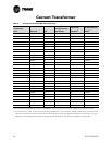
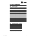
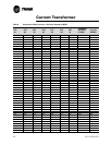
steady state overload setting is fixed at 132%). Refer to Tables 5 thru 9 for
setup details.
The current transformers provide the input for six basic functions of the
MCSP:
1. Motor overload protection using a programmed “% RLA versus time to
trip” characteristic. Refer to Table 6 for details. The steady state “must
trip” value is 140% RLA and the “must hold” value is 125% RLA. The
MCSP will trip out the compressor. The appropriate diagnostic descrip-
tions are then displayed in the CLD diagnostic section.
2. Verifying contactor drop-out. If currents corresponding to less than 12
±7% RLA are not detected on all three of the monitored compressor
phases within approximately 5 seconds after an attempted contactor
drop-out, the compressor will continue to be commanded Off, the Unload
solenoid will be pulsed, the EXV will be opened to its fullest position, and
the fans will continue to be controlled. This condition will exist until the
diagnostic is manually reset.
3. Loss of Phase Current. If the detection of any or all of the three motor
phase currents falls below 12 ±7% RLA for 2 ±1 seconds while the
branch circuit should be “energized”, the MCSP will trip out the compres-
sor. The Phase Loss diagnostic, or the Power Loss diagnostic, will be dis-
played. Failure of a contactor to pull in will cause the Phase Loss
diagnostic. However when reduced voltage starting is employed, it may
take an additional 3 seconds to detect a phase loss at startup, as phase
loss protection is not active during the 3 second transition time.
4. Phase Rotation. Screw compressors cannot be allowed to run in reverse
direction. To protect the compressors, the phase rotation is detected by
the current transformers immediately at start up. If improper phasing is
detected, within 1 second of startup, the MCSP will trip out the compres-
sor. The Phase Rotation diagnostics will be displayed. This function is not
sensitive to the current transformer's polarity.
5. Phase Unbalance. The MCSP will shut down the compressor if a phase
current unbalance is detected by the current transformers while the com-
pressor is running. A 15% unbalance, if protection is enabled, will cause
the MCSP to trip out the compressor. The Phase Unbalance diagnostics


