74 RLC-SVD03A-EN
Module Power and Miscellaneous I/O
the currents are higher than actual and will show up as an error in the %RLA
displayed by the CPM. The compressor will operate safely but may unload
due to the current limit function.
Refer to Current Transformers and Current Inputs for more details on
operation and troubleshooting.
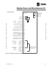
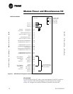
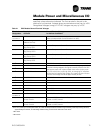
Isolated Binary Input: Winding Temperature
This input may be checked by disconnecting all wiring from the terminals and
measuring the open circuit voltage. It should read between 10 and 15 Vac. A
“Winding Temp. - Cprsr A or B” diagnostic should appear on the CPM's
display depending on which compressor module it is. A jumper may then be
placed across the input to short it out. After clearing diagnostics, the
diagnostic should no longer be present. It a diagnostic continues to occur, the
module needs replacement.
Relay Outputs
Compressor and Fan Control relays may be checked by measuring the voltage
drop across the contacts. 115 Vac should be seen when the relay is off. 0 Vac
should be seen when the relay is on. Before condemning a module for bad
relays, make sure to check all diagnostics, power to the module, communica-
tions, and the state of the high pressure cutout. Refer to the units' schematic
wiring diagram for the control circuitry.
Triac Outputs
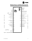
The Load/Unload triacs may be checked by measuring the voltage from
terminals E7 or E8 to 115 V neutral, with a load connected. The triacs operate
in the high side and switch 115 Vac power from J7-1 to either E7 or E8 to turn
on the appropriate slide valve solenoid.
When a triac is off, about 0 Vac should be measured on its terminal with the
solenoid load connected. When it is on, the voltage should be close to 115
Vac (the drop across the triac is about 1-2 volts). Except during a start or stop,
the triacs normally pulse on for short durations (as low as 40mS) once every
10 seconds. If chiller load is satisfied the triacs may not pulse. Because of
this, it may be difficult to see the pulses on a meter. A low wattage 115 Vac
test lamp may be of help.
The best time to check the unload solenoid is immediately after a power-up
reset. For the first 30 seconds after applying power, the unload solenoid
should be on continuously. The next best time to check it is after the
compressor starts. For the first 30 seconds after a start, the unload solenoid
should be on continuously.
Checking the load solenoid is more difficult. Shortly after a start, the
compressor will usually start loading. If, however, water temperature is
dropping rapidly enough, it will stay unloaded. It may take a while to begin
seeing load pulses.
Refer to on page 36, for a more detailed procedure on how to accomplish the
load / unload solenoid and slide valve check on the MCSP and associated
compressor.


