46 RLC-SVD03A-EN
Module Power and Miscellaneous I/O
When updating is successfully completed, the system will default to the first
display after the Chiller Report header:
MODE: OPERATING MODE]
REQUESTED SETPOINT SOURCE: [SETPT SOURCE]
and the backlight will be activated.
LEDs
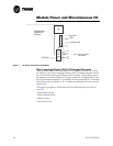
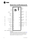
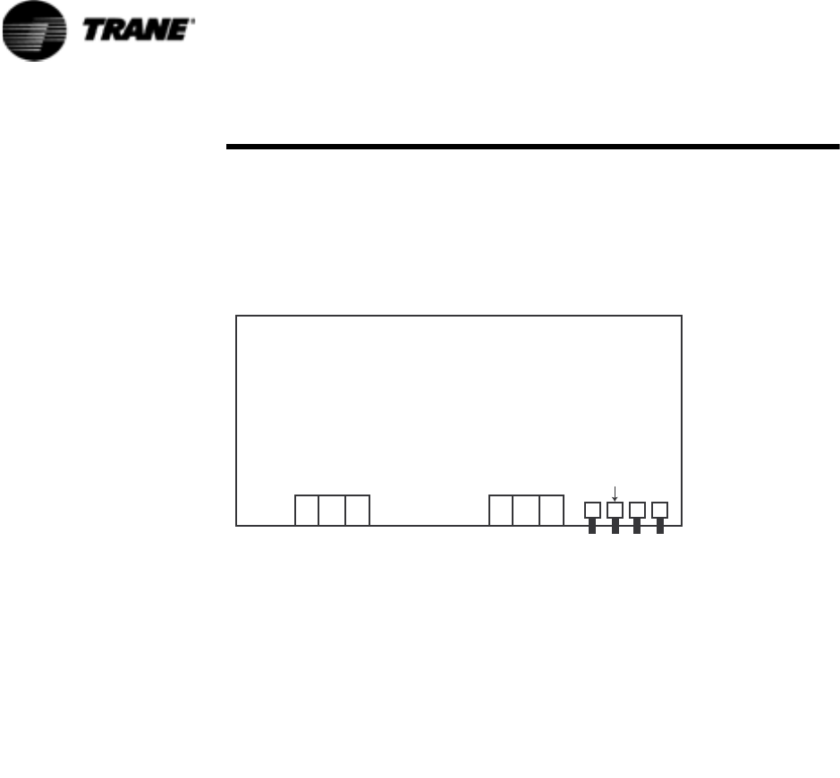
There are four LEDs located to the right of TB1 of the CLD module. See
Figure 9. The ST LED should be on continuously. If it blinks, it indicates the
processor is repeatedly being reset. The +5 VDC LED should also be on
continuously. It will go out if power drops below normal operating voltage.
The TX LED should blink every second or two, as the CLD transmits on the
IPC. The RX LED should blink continuously, indicating that other modules are
communicating.
Chiller Module (CPM) (1U1)
ƽ WARNING
Live Electrical Components!
During installation, testing, servicing and troubleshooting of this
product, it may be necessary to work with live electrical
components. Have a qualified licensed electrician or other
individual who has been properly trained in handling live
electrical components perform these tasks. Failure to follow all
electrical safety precautions when exposed to live electrical
components could result in death or serious injury.
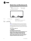
TB1-1,2 IPC Communications 19.2K Baud serial data
5 V signal level
Refer to Interprocessor Communication (IPC)
TB2-1,2 24 VAC Power 18-30 VAC, neither side grounded
Figure 9 CLD Module (1U6)
9$&
7%
$%* *
9'&
7;67 5;
7%


