


42 UV-SVP01A-EN
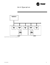
Unit Operation
seconds. This provides the ample
torque required to start all fan mo-
tors from the off position.
Exhaust fan/damper
operation
This binary point is a shared point
with medium fan speed. For this
point to be used for exhaust con-
trol, the controller must be config-
ured for a 1- or 2-speed fan. The
exhaust fan/damper is coordinated
with the unit fan and outdoor
damper operation. The exhaust
output is energized only when the
unit fan is operating and the out-
door damper position is greater
than or equal to the configurable
exhaust enable point. The exhaust
fan output is disabled when the
outdoor air damper position drops
10% below the exhaust enable
point. If the enable point is less
than 10%, the unit turns on at the
enable point and off at 0.
Valve Operation
Modulating Valves
The Tracer ZN.520 controller sup-
ports one or two modulating
valves for hydronic heating and
cooling operation. The main valve/
coil is used for cooling only, heat/
cool changeover (2-pipe applica-
tions), or cooling (4-pipe applica-
tions). The auxiliary valve/coil
provides heating in 4-pipe and
heating only applications.
At power-up, the Tracer ZN.520
controller drives the modulating
valves to the closed position. The
controller calibrates to the full
closed position by overdriving the
actuator 135%. Whenever the con-
troller requests a valve position of
zero or 100%, the controller over-
drives the actuator 135% regard-
less of the current valve position.
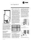
Face-and-Bypass
Isolation Valves
Face-and-bypass units may use
isolation valves to prevent unwant-
ed water flow in the coil. This elim-
inates problems such as radiant
heat or excessive condensate in 2-
pipe systems.
In 4-pipe applications, the isolation
valves are used to prevent conflict-
ing capacities within the unit.
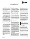
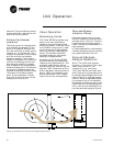
Face-and-Bypass
Damper Operation
Note: The Face-and-bypass
actuator is located in the right-
hand end pocket of the
classroom unit ventilator.
The Tracer ZN.520 controller actu-
ates a face-and- bypass damper to
modulate a percentage of air to the
face of the coil to maintain space
comfort. When a requested capaci-
ty is present, the unit modulates
the damper to allow more air to the
face of the coil. An averaging sen-
sor is used on the discharge air to
provide accurate capacity control.
Figure 18: Horizontal unit with face-and-bypass damper option.