


10 UV-SVP01A-EN
Controller Features
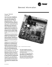
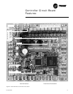
Each Tracer ZN.520 unit controller
circuit board is equipped with en-
hancements to help facilitate ser-
vice, testing, and diagnosis.
Each board has
q Manual test button,
q Status LED,
q Communication status LED,
q Service button,
q Quick terminal connectors, and
q Easy to read screen printing.
(See Figure 1: “Tracer ZN.520
Control Board”).
Service
The Trane Tracer ZN.520 unit con-
troller is serviced using Rover
®
, the
ICS software service too. Rover is
designed to support the Tracer
ZN.520 unit controller on the class-
room unit ventilator.
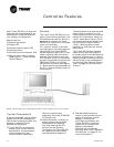
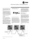
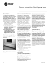
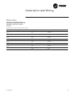
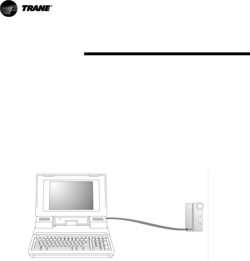
For “remote” access to the com-
municating units, the zone sensors
offered with the Tracer ZN.520
have a telephone style (RJ-11) con-
nector allowing field connection
between Rover and the zone sen-
sor; however, the RJ-11 connector
must be connected to the terminals
TB2-5 and TB2-6 on the Tracer
ZN.520 unit controller.(See Figure
3: “Rover service tool connected to
the RJ-11 communication jack in a
zone sensor”)
The zone sensor may also be used
when trying to locate a unit. By
pressing the ON button on the zone
sensor for 5 seconds or using the
“wink” command in Rover, the cir-
cuit board receives the signal caus-
ing the Communication LED to
“wink”. Winking allows visual
identifier on the board for service
technicians.
The Tracer ZN.520 also includes
features such as a test output to
manually test all of the end devices
and color coded wires (i.e. red for
heating valves and blue for cooling
valves) to aid in the troubleshoot-
ing process.(See “Manual Output
Test” on page48, for more infor-
mation.)
Figure 3: Rover service tool connected to the RJ-11 communication jack in a zone sensor
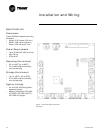
Typical Components
A typical classroom unit ventilator
system with a DDC package con-
sists of the following physical com-
ponents, in addition to the
mechanical equipment:
q Tracer ZN.520—contains the
sensor input circuits, service
adjustments, microprocessor
control electronics, and
communications hardware.
Power is supplied by a
separately mounted 24 VAC\90
VA transformer.
q Sensor Modules—a variety of
analog sensors that provide
temperature and optional
humidity sensing and CO
2
sensor; and an operator
interface to the Tracer ZN.520
for operating modes, status,
and temperature setpoints.
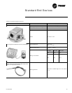
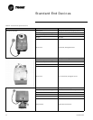
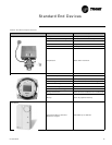
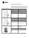
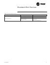
q Standard End Devices—a
variety of devices that help to
gather information, control
capacity, and provide
ventilation are used by the
Tracer ZN.520 in its control
algorithm to condition the
space to the desired
temperature and relative
humidity level. (See “Standard
End Devices” on page13, for
more information.)