UV-SVP01A-EN 11
Communication Configurations
Note: The Tracer ZN.520 is a
configured controller. It will
not operate without a valid
downloaded configuration
file.
The Tracer ZN.520 controller sup-
ports ICS and peer-to-peer com-
munications as well as stand-
alone operation. A number of con-
trol features may be configured at
the factory or by using the Rover
service tool. (See “Configuration”
on page32, for more information.)
Integrated Comfort
System
Note: The Tracer ZN.520
controller may only be used
with Tracer Summit version
11.0 or greater with a Comm5
communications card.
Classroom unit ventilators can op-
erate as part of a large building au-
tomation system controlled by
Tracer Summit. The Tracer ZN.520
is linked directly to the Tracer
Summit via a twisted pair commu-
nication wire. Each Tracer Summit
building automation system can
connect to a maximum of 120
Tracer ZN.520 controllers.
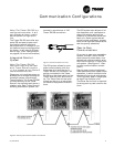
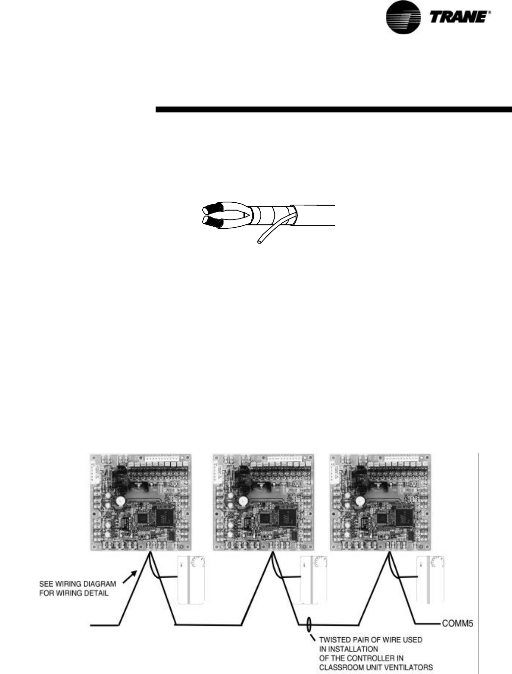
Figure 4: Communications link wire
The ICS system allows for com-
plete communication with the
classroom unit ventilators via
Tracer ZN.520 unit controller. All
points connected to the Tracer
ZN.520 may be observed from the
Tracer Summit front-end control-
ler. The Tracer Summit can also
initiate an alarm on a loss of per-
formance or equipment malfunc-
tions.
The ICS system also allows all of
the classroom unit ventilators to
share information without the
presence of hardwired sensors at
each unit. Some typical shared
points include outside air temper-
ature, entering water temperature,
and occupancy schedules.
Peer-to-Peer
Communications
On a peer-to-peer communication
system, multiple Tracer ZN.520
controllers may share data, via a
twisted pair communication wire,
without the need for a Tracer Sum-
mit system. (See Figure 5: “Peer-
to-peer communication connec-
tions”)
Peer-to-peer communications al-
lows features such as master/slave
operation, in which multiple units
operate off of a single zone sensor.
This is typically seen in large spac-
es requiring multiple units.
The Rover service tool is required
to set up peer-to-peer communica-
tions.
Figure 5: Peer-to-peer communication connections


