


• From the dryer, the refrigerant flows through the capillary tube which meters the liquid refrigerant to
the evaporator. The pressure of the refrigerant is reduced to the evaporating or low side pressure.
• The reduction of pressure on the liquid refrigerant causes it to boil or vaporize until it reaches satura-
tion temperature. As the low temperature refrigerant passes through the evaporator coil, it continues to
absorb a lot of heat, causing the boiling action to continue until the refrigerant is completely vapor-
ized. It is during this phase change that the most heat is absorbed (the cooling takes place) in the refrig-
erator.
• The refrigerant vapor leaving the evaporator travels through the suction line to the compressor inlet.
The compressor takes the low pressure vapor and compresses it, increasing both pressure and tempera-
ture. The hot high pressure gas is pumped out the discharge line and into the condenser. The cycle
continues.
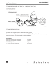
THERMISTORS
The two thermistors sense the two compartment temperatures. This is used in conjunction with the control
board to determine the length of the refrigeration cycle.
Thermistors generally fail due to moisture or physical damage.
SERVICE NOTES
2075DWRWC
The 2075DWRWC has the same basic refrigeration system as the 2075R/2075WC with a few exceptions.
• The compressor is a high efficiency Embraco EMU30HSC.
• The electro-mechanical gas bulb is replaced with an electronic controller. The 2075DWRWC features
an LED display and touch sensors for each drawer and a touch sensor to control the lighting.
• There are two interior lights and light switches which can be controlled independently from each
other. The switches are mounted in the liner in the rear interior of the cabinet and the lights, in a
housing in the top front of the drawers.
This unit is operated with a two part electronic control assembly. The main board is located in the base of
the unit behind the grille and the display board is permanently attached to the glass in the upper drawer.
There is a snap in access panel in the drawer to reach the back of the board.
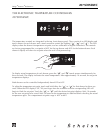
The LED display indicates the set point of both compartments. Holding either the up or down arrow for
three seconds enters into the set point mode. You can adjust the temperature of each compartment
independently from 40-60°F.
Holding both the up and down arrow for either section displays the actual temperature.
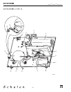
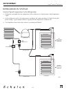
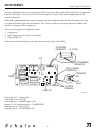
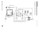
When the unit is plugged in the top compartment begins cooling first. After the top set point has been
reached the lower compartment will begin cooling. Only one drawer can cool at a time. One compressor
and condenser are used in this system. Behind the compressor are two valves that switch the refrigerant
from the top system to the bottom system. Each system has a bypass valve, dryer, evaporator and capillary
tube. Only one system can operate at a time.
2075DWRWC
25
Design
■
Features
■
Performance