


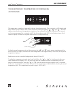
The top and bottom valve can never be open at the same time. After initial startup whichever compartment
calls for cooling first, will have priority. Once the setpoint is achieved the other compartment will be
cooled if necessary.
When both compartments have reached setpoint and the compressor shuts off, the last bypass valve that
was open will remain open for four minutes. This is done to help the refrigerant pressures stabilize and
reduce hard starting of the compressor.
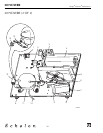
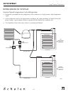
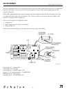
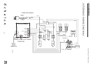
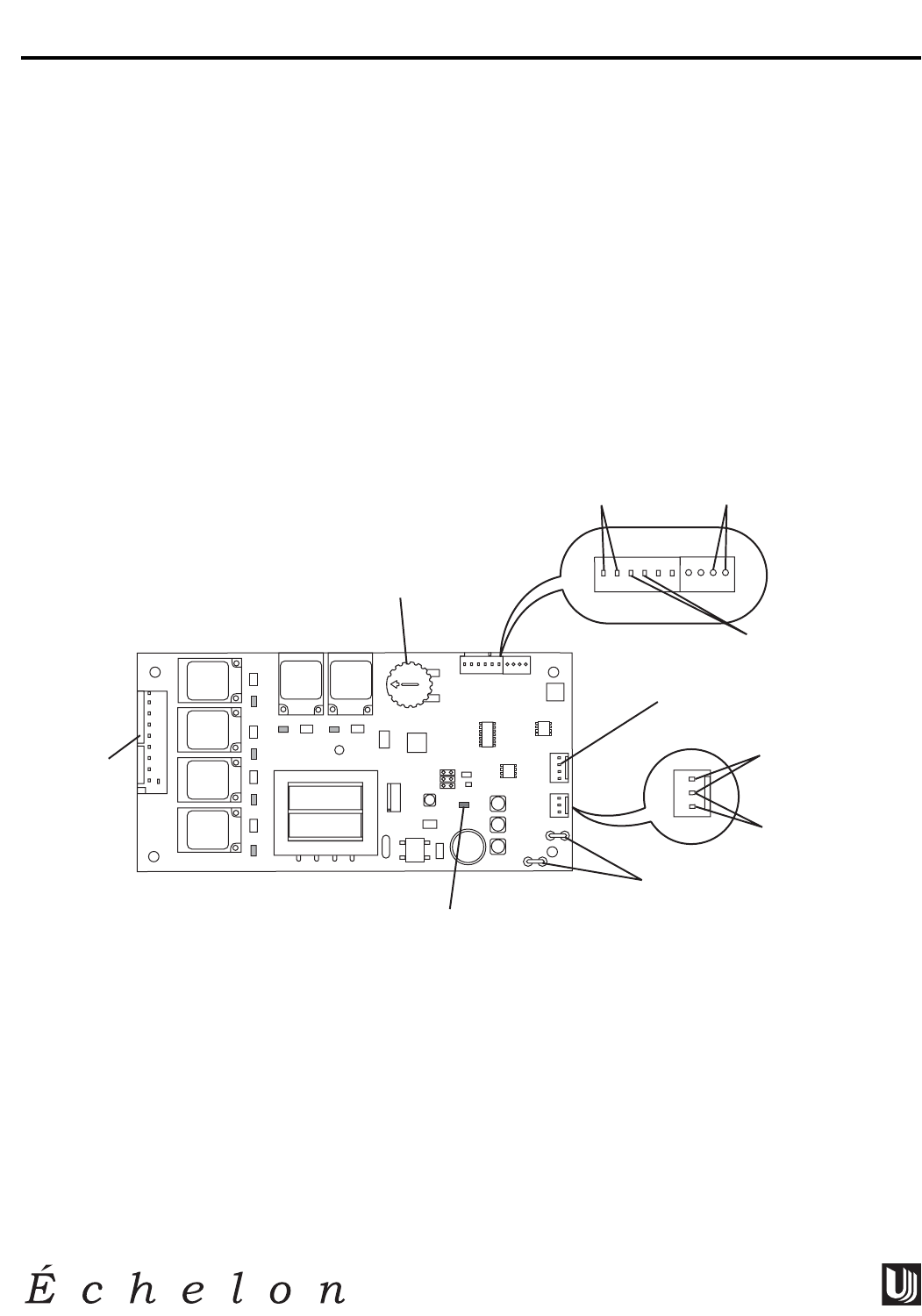
This unit can be put into a diagnostic mode.
1. Unplug unit
2. Install jumper on pins 9 and 10 on board.
3. Plug unit back in.
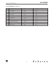
Based on the attached chart you can turn on and off each relay individually.
Control pot at 2 – bottom light
Control pot at 0 – top light
Control pot at -2 – bottom bypass valve
Jumper on 1/4" spade terminals – COMPRESSOR
Jump pins on J2 – TOP VALVE
Jump pins on J2 – CONDENSER FAN
CLRCO035C
-1
-2
-3
-4
-5
5
4
3
2
1
0
TOP
VALVE
BOTTOM
VALVE
TOP
LIGHT
COMPRESSOR
COND/GAS
FAN
BOTTOM
LIGHT
12345678910
1/4" SPADE
TERMINALS
POWER ON
9 & 10 PINS
POT
POWER
J2
TOP
VALVE
CONDENSER
FAN
DISPLAY BOARD
CONNECTION
BOTTOM DRAWER
THERMISTOR
TOP DRAWER
THERMISTOR
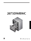
2075DWRWC
26
Design
■
Features
■
Performance