


6
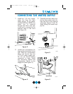
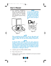
User’s Manual
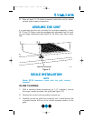
NOTE
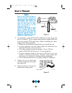
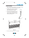
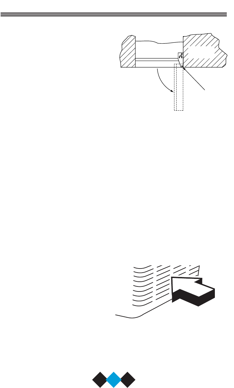
Keep in mind that the door of
the unit may be mounted on
either side of the cabinet (see
REVERSING THE DOOR). All
U-Line units have a zero clear-
ance for the door to open
when the handle is on the
right (see Figure 1).
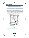
Additional clearance is need-
ed for Combo Models 29A,
29FF, and 75A only, when the
door handle is on the left. See
BUILT-IN INSTALLATION for
additional clearance require-
ments for these models.
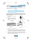
3. On Ice Maker models SP18, BI-95, BI-98 and Combo Series 29
and 75, install a 1/4 inch copper water line (not supplied with unit)
from the nearest COLD water pipe. When connecting the water
supply, follow these guidelines:
• Review the local plumbing codes before you install the unit.
• In most instances, the cold water supply will come from the
basement through a hole in the floor.
• The water pressure should be between 15 and 150 psi.
• Install a SHUT-OFF VALVE in the 1/4 inch supply line.
• Connect sufficient tubing to the unit to allow the unit to be
moved for cleaning and servicing. However, make certain that
the tubing is not pinched or damaged during installation.
• U-Line recommends the use of copper tubing for installation.
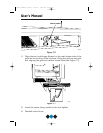
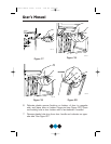
4. Position the unit to allow free
air flow through the front grille
(see Figure 2).
5. Wipe out inside of unit and ice
bucket with a damp cloth.
UL005A
UL124
DOOR
SWING
CABINET
OR WALL
0"
CLEARANCE
NEEDED
Figure 1
Figure 2
Users Manual 41923 9/2/03 3:44 PM Page 6