


10 SS1095
MARINE SERIES
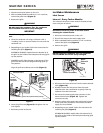
SS1095FD model: Align the tabs on the bottom of the
grille with the slots in the flange and swing grille up
into position.
Align the grille and cabinet screw holes
(Figure 8)
.
10. Insert the grille screw
(Figure 8)
and tighten. Do not
over-tighten.
11. Reconnect power to the unit.
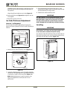
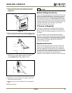
Ice Cube Thickness Adjustment
Interval - As Required
The ice cube size may be adjusted by changing the
amount of water injected into the ice maker assembly as
follows:
Figure 11
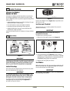
1. Remove the ice maker assembly cover (Figure 11).
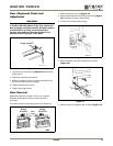
Figure 12
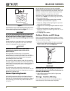
2. Locate the adjusting screw on the ice maker assembly
control box. The adjusting screw is just below the minus
(-) and plus (+) signs on the control box
(Figure 12)
.
NOTE: Make adjustments in small increments. Too
large of an adjustment could cause the unit to
malfunction.
3. Turn the adjusting screw toward the minus (-) sign
(clockwise) for smaller cubes or toward the plus (+) sign
(counterclockwise) for larger cubes.
4. Install the ice maker assembly cover.
IMPORTANTIMPORTANT
Use only genuine U-Line replacement parts. U-Line
ice maker parts are not the same as standard FSP
Whirlpool parts. Using non U-Line parts can reduce
ice rate, cause water to overflow from ice maker
mold, damage the unit and may void the warranty.
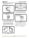
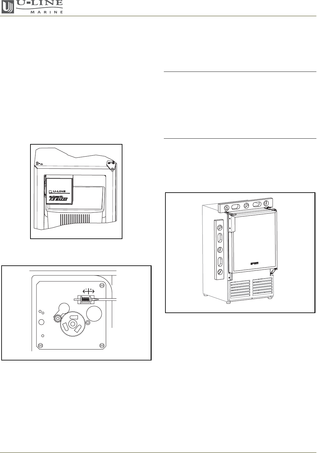
Leveling
IMPORTANTIMPORTANT
It is extremely important that the unit sits on a
level surface, as it does not have feet levelers. If it
is not level, the ice mold will not fill evenly.
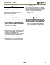
Use a level to check the levelness of the unit from front to
back and from side to side. Level should be placed along
top edge and side edge as shown (Figure 13).
Figure 13
ULIN_0237_A
ULIN_0056_A
ULIN_1047_A