


22 OM/SM-HY-6E(CE)
OM/SM-HY-6E(CE)
22
5. Attach new drain valve to valve bracket. Pull silicone
hose through drain valve and loosely install hose
clamps over both ends of the hose. Be sure silicone
hose is properly aligned and does not have any
kinks, bends and/or twists.
6. Position the valve over the valve mounting threaded
studs and connect both ends of the hose to the drain
box and steam generator.
7. Position the clamps so that the worm screw may be
easily tightened. Using a 7mm nutdriver, tighten both
hose clamps. Be careful not to overtighten clamps as
it may cut hose.
8. Install and tighten valve mounting 10-32 cap nuts.
9. Plug valve electrical leads into the wiring harness.
To Test:
Operate steamer and allow steam generator to fill. Check
for leaks and observe if drain valve fully closes. Turn off
steamer and observe that drain valve opens and the
steam generator drains. Install back cover.
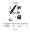
10.6 Water Inlet Valve - Three Way
P/N 090827
1. Turn off power to the steamer. Turn off the water
supply to the steamer. Remove the water supply
hose connection on the rear of the steamer.
2. As viewed from the rear, remove the back panel and
the right panel.
3. The water inlet of the valve branches to three
individual solenoid activated valves within a single
housing, with the following sets of wires:
Solenoid
Wires
Top Steam Generator Fill: Green and Blue
Bottom Steam Generator Fill: Violet and Gray
Condensate Spray: Black and White
4. Using a 7mm nutdriver, loosen the three hose
clamps on the water inlet valve.
5. Slide the hose clamps down the hose until needed
for reassembly. Loosen and remove the hoses using
a gentle rocking motion.
6. From the back of the steamer, remove the two
screws holding the valve assembly in place. Then
lower the valve WITH THE WIRES STILL
ATTACHED.
7. From the back of the steamer, remove the two 8-32
screws holding the valve assembly in place. Lower the
valve.
8. Carefully unplug the connectors, one at a time and
attach to the new valve.
9. To install a new valve, reverse the procedures and
first install the six wires (three sets) as listed in Item 3
of this Section. Fasten the valve to the steamer with
the two screws. Make sure that the valve is NOT
installed upside down.
10. Re-attach the hoses to the valve. Slide the hoses all
the way so that the end of the hose is flush against the
face of the valve.
IMPORTANT. Make sure that the correct steam generator
hose is connected to the corresponding valve outlet. Slide
the hose clamps back into position around the end of the
hose and tighten the clamps.
CAUTION: Do not overtighten these clamps as that may
damage the valve.
Slide the hose clamps so that they are within 1/8 inch (3
mm) from the end of the hose.
TOP hose — to the TOP Steam Generator
MIDDLE hose — to the BOTTOM Steam Generator
BOTTOM hose — to the DRAIN Box
11. Attach the three sets of wires to the valve making sure
that the proper wires are connected to the
corresponding terminals.
To Test:
With power ON, turn on the power switch to one cavity.
The fill solenoid for that steam generator should energize
allowing water to enter the steam generator. When
READY light is ON, spray valve solenoid should energize
and water should enter the drain box.
10.7 Water Inlet Valve Coil
If a solenoid coil on the water inlet valve is defective,
replace the entire valve in accordance with Section 10.6.
10.8 Drain Box Spray Nozzle
P/N 081670
1. Raise the stainless steel vent pipe to remove it from
the drain box. Do not loosen the hose clamp around
the vent pipe. The hose clamp serves to prevent the
pipe from going too far into the drain box. Secure the
vent pipe in the raised position.