


OM/SM-HY-6E(CE) 27
OM/SM-HY-6E(CE)
27
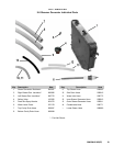
13. The entire assembly may now be positioned on the
four threaded stud bolts protruding from the cavity
wall. Fasten the assembly with the 1/4-20 Keps nuts
using a socket wrench. Make sure that the green
ground strap is fastened by one of the Keps nuts
securing the motor.
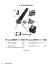
10.19 Motor Starting Capacitor
P/N 096813
1. Turn off electrical power to the steamer.
2. Loosen and remove the screw holding the capacitor.
3. Unplug the two terminal wires from the capacitor.
Remove the capacitor.
To Install New Capacitor:
NOTICE: Make sure that the correct capacitor is
used, which is 3 mfd at 330 volt. This capacitor is
different from that used on Model HY-6G.
4. Make sure the capacitor is seated properly, then
tighten the screw securing the capacitor to the
mounting plate.
5. Plug terminal wires to the capacitor.
10.20 Steam Generator Ready Thermostat
P/N 088865
This thermostat is attached to the cavity steam port by
two 6-32 screws.
1. Turn off power to the steamer.
2. Unplug the two wires from the thermostat from the
wiring harness.
3. Using a flat blade screwdriver, remove the two
screws holding the thermostat to the steam port.
4. To install a new thermostat, use a small amount of
heat sink compound (1 drop), applied to bottom of
thermostat. Seat the thermostat on the steam port
and fasten with the two screws (as above).
5. Plug the thermostat into the wiring harness.
10.21 Steam Port Gasket
P/N 096736 P/N 099250
1. Shut off power to the steamer.
2. Remove the 1-1/8 inch steam hose by loosening the
clamp around the hose and sliding it away from the
steam port. Loosen hose and remove from steam
port.
3. With a flat blade screwdriver, remove the two 6-32
screws holding the thermostat to the steam port.
4. With a sharp knife or small scissor, cut the aluminum
foil insulation blanket as shown at left.
5. Fold up aluminum foil insulation blanket to expose the
two 1/4-20 Keps nuts which hold the steam port to the
cavity wall threaded studs.
6. With a socket wrench, remove the two Keps nuts.
7. Remove the steam port from the threaded studs.
To Install:
8. Put a small bead of silicone sealant in and around the
groove in the steam port to seal any possible leaks, or
use gasket P/N 099250.
9. Install steam port on threaded studs. Secure with two
Keps nuts.
10. Fold down aluminum foil insulation blanket to original
blanket position and repair cuts with aluminum foil
duct tape.
11. Reinstall thermostat as described in 10.20 above.
12. Reinstall steam hose to steam port and install the
clamp.
10.22 Cavity Steam Hose Assemblies
P/N 099952 (Top)
P/N 099951 (Bottom)
There are two hoses which connect the steam generators
with their respective cavities. One for the top cavity and
one for the bottom cavity. If both hoses are to be replaced,
replace them one at a time.
1. Shut off power to the steamer.
2. Remove cavity side and lower side panels of table.
3. In the upper portion of the steamer, remove hose.
Turn and pull the hose to remove it from the hose
nipple.
4. In the lower section of the steamer, remove the hose
clamp from where the hose is connected to the steam
generator. Turn and pull the hose to remove it from
the hose nipple.