


26 OM/SM-HY-6E(CE)
OM/SM-HY-6E(CE)
26
corresponding hole punched into the front panel. This
hole may be seen from the inside of the compartment
only when the timer is removed.
To Install:
6. Fit the timer in place making sure that it is properly
placed so that the disk on the timer fits into the
punched hole in the front panel.
7. Once the timer is properly located, tighten the hex
nut so that the timer does not slip or rotate. Do not
overtighten the nut.
8. Align the flat of the knob hole with the flat on the
timer shaft. Press the knob firmly onto the timer
shaft.
9. Plug in the wires identified above and connect the
two black wires from the motor leads.
10. Reattach the control panel cover.
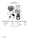
10.17 Fan
P/N 096790
IMPORTANT: Make sure that the fan has come to a
complete stop before attempting any work on the fan.
1. To remove the fan from either the top or bottom
cavity, open the door and remove the pan support
wire rack in front of the fan.
2. With an allen wrench, loosen the set screw which
holds the fan to the motor shaft.
3. Hold onto the fan, and with a slight rocking motion
pull the fan off the motor shaft.
To Install:
4. Note that the motor shaft has a flat surface. Position
the fan hub on the motor shaft so that the allen set
screw is opposite the flat portion of the motor shaft.
5. Slide the fan onto the motor shaft far enough so that
the motor shaft is at the end of the fan hub.
6. With an allen wrench, tighten the set screw on the
fan.
NOTICE: Advise customer to periodically clean the fan
blades of deposited food grade grease coming from the
foods being cooked. The deposit of such grease over
time could cause the fan to vibrate.
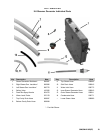
10.18 Fan Motor Assembly Motor Insulation
P/N 096740 P/N 094135
Motor Shaft Seal Oil Slinger Washer
P/N 096868 P/N 096831
1. Shut off electrical power to the steamer.
2. From inside the cavity, remove fan using an allen
wrench as indicated in Section 10.17.
3. Using a socket wrench, remove the four 1/4-20 Keps
nuts holding the motor. Note that one of the nuts
secures the motor ground strap to the steamer.
4. Pull the printed circuit mounting plate forward to clear
the lower two threaded studs securing the motor.
5. Remove the motor mounting plate to which the motor
is attached.
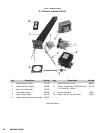
To Install a New Motor:
6. Make sure the motor insulation board is installed on
the four threaded studs to the cavity wall.
7. Apply lubricant on both sides of the steamer motor
seal and the inside hole. Refer to the Motor Assembly
Chart.
8. Insert the steamer motor seal in the cutout of the
insulator board.
9. To prepare motor for mounting, slide the oil slinger
washer onto the shaft about ½" (12 mm) down the
shaft.
IMPORTANT: This washer has two surfaces: A rubber
surface and a phenolic
surface. Make sure the
phenolic surface is facing the motor.
10. Install the plate seal holder onto the motor shaft.
Carefully slide the plate seal holder down the motor
shaft until it engages the slinger washer. Continue
moving the plate seal holder down the motor shaft
until the plate comes to rest on the raised bosses of
the motor casting.
11. Using this technique, the rubber side of the oil Slinger
washer should be in contact with the plate holder and
there should be a space of approximately 5/64" (2
mm) between the phenolic face of the washer and
the motor.
12. Using four hex/slotted 6-32 screws, screw the motor
mounting plate to the motor with each screw passing
through corresponding holes in the plate seal holder.