


16
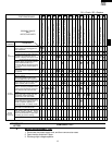
CDMOS200
DMOS200
VMOS200
CVMOS200
TEST PROCEDURES
PROCEDURE
LETTER
COMPONENT TEST
1. Disconnect the power supply cord, and then remove outer case.
2. Open the door and block it open.
3. Discharge high voltage capacitor.
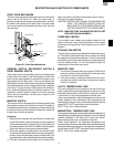
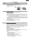
4. Before performing this test, make sure that the primary switch is operating properly, according to the
above Switch Test Procedure. Disconnect the wire lead from the monitor switch (COM) terminal. Check
the monitor switch operation by using the ohmmeter as follows. When the door is open, the meter should
indicate a closed circuit. When the monitor switch actuator is pushed by a screw driver through the lower
latch hole on the front plate of the oven cavity with the door opened (in this condition the plunger of the
monitor switch is pushed in), the meter should indicate an open circuit. If improper operation is indicated,
the switch may be defective. After testing the monitor switch, reconnect the wire lead to the monitor
switch (COM) terminal and check the continuity of the monitor circuit.
CAUTION: IF THE TEMPERATURE FUSE INDICATES AN OPEN CIRCUIT AT ROOM TEMPERA-
TURE, REPLACE TEMPERATURE FUSE.
1. Disconnect the power supply cord, and then remove outer case.
2. Open the door and block it open.
3. Discharge high voltage capacitor.
4. Isolate the switch and connect the ohmmeter to the common (COM.) and normally open (NO) terminal
of the switch. The meter should indicate an open circuit with the door open and a closed circuit with
the door closed. If improper operation is indicated, replace the secondary interlock switch.
5. Reconnect all leads removed from components during testing.
6. Reinstall the outer case (cabinet).
7. Reconnect the power supply cord after the outer case is installed.
8. Run the oven and check all functions.
SECONDARY INTERLOCK SYSTEM TEST
DOOR SENSING SWITCH
1. Disconnect the power supply cord, and then remove outer case.
2. Open the door and block it open.
3. Discharge high voltage capacitor.
4. Isolate the switch and connect the ohmmeter to the common (COM.) and normally open (NO) terminal
of the switch. The meter should indicate an open circuit with the door open and a closed circuit with
the door closed. If improper operation is indicated, replace the door sensing switch.
5. Reconnect all leads removed from components during testing.
6. Reinstall the outer case (cabinet).
7. Reconnect the power supply cord after the outer case is installed.
8. Run the oven and check all functions.
NOTE: If the door sensing switch contacts fail in the open position and the door is closed, the cooling fan,
turntable and oven light will be activated by RY1.
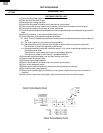
SECONDARY INTERLOCK RELAY (RY2)
1. Disconnect the power supply cord, and then remove outer case.
2. Open the door and block it open.
3. Discharge high voltage capacitor.
4. Disconnect two (2) wire leads from the male tab terminals of the Secondary Interlock Relay. Check the
state of the relay contacts using a ohmmeter. The relay contacts should be open. If the relay contacts
are closed, replace the circuit board entirely or the relay itself.
5. Reconnect all leads removed from components during testing.
6. Reinstall the outer case (cabinet).
7. Reconnect the power supply cord after the outer case is installed.
8. Run the oven and check all functions.
F PRIMARY AND SECONDARY SWITCH TEST
G MONITOR SWITCH TEST