


24
CDMOS200
DMOS200
VMOS200
CVMOS200
TOUCH CONTROL PANEL ASSEMBLY
OUTLINE OF TOUCH CONTROL PANEL
4) Relay Circuit
A circuit to drive the magnetron, fan motor, turntable
motor and light the oven lamp.
5) Buzzer Circuit
The buzzer is responsive to signals from the LSI to emit
audible sounds (key touch sound and completion sound).
6) Synchronizing Signal Circuit
The power source synchronizing signal is available in
order to compose a basic standard time in the clock
circuit.
It accompanies a very small error because it works on
commercial frequency.
7) Door Sensing Switch
A switch to “tell” the LSI if the door is open or closed.
8) Back Light Circuit
A circuit to drive the back light (Light emitting diodes
LD10- LD15).
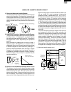
9) Absolute Humidity Sensor Circuit
This circuit detects moisture of the cooking food to allow
its automatic cooking.
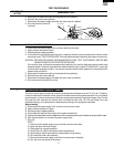
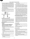
The touch control section consists of the following units.
(1) Key Unit
(2) Control Unit (The Control Unit consists of Power Unit
and LSI Unit).
The principal functions of these units and the signals commu-
nicated among them are explained below.
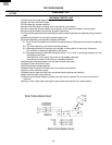
Key Unit
The key unit is composed of a matrix, signals generated in the
LSI are sent to the key unit through P00-P07.
When a key pad is touched, a signal is completed through the
key unit and passed back to the LSI through P14, P15, P16,
P17, AIN6 and AIN7 to perform the function that was
requested.
Control Unit
Control unit consists of LSI, ACL circuit, indicator circuit,
power source circuit, relay circuit, buzzer circuit, synchroniz-
ing signal circuit, absolute humidity sensor circuit and back
light circuit.
1) ACL
This circuit generates a signal which resets the LSI to the
initial state when power is supplied.
2) Indicator Circuit
This circuit consists of 40 segments and 16 common
electrodes using a Liquid Crystal Display.
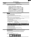
3) Power Source Circuit
This circuit generates voltages necessary in the control
unit from the AC line voltage.
In addition, the synchronizing signal is available in order
to compose a basic standard time in the clock circuit.
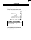
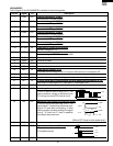
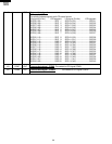
Symbol Voltage Application
VC -5V LSI(IC1)