


27
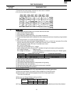
CDMOS200
DMOS200
VMOS200
CVMOS200
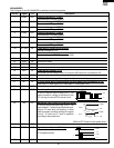
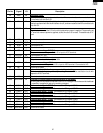
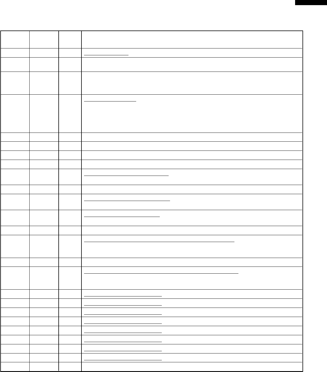
49 AIN5 IN AH sensor input.
This input is an analog input terminal from the AH sensor circuit, and connected to the A/
D converter built into the LSI.
50 AIN4 IN Used for initial balancing of the bridge circuit (absolute humidity sensor). This input is an
analog input terminal from the AH sensor circuit, and connected to the A/D converter built
into the LSI.
51 RESET IN Auto clear terminal.
Signal is input to reset the LSI to the initial state when power is applied. Temporarily set
"L" level the moment power is applied, at this time the LSI is reset. Thereafter set at "H"
level
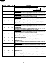
52 NC
_
Terminal not used.
53 XCOUT OUT Terminal not used.
54 XCIN IN Connected to VC.
55 NC
_
Terminal not used.
56 VCC IN Power source voltage: GND(0V).
The power source voltage to drive LSI is input to VCC terminal.
57 OSCSEL IN Connected to VC(-5V).
58 XOUT OUT Internal clock oscillation output.
Output to control oscillation input of XIN.
59 VSS IN Power source voltage: -5.0V.
The power source voltage to the LSI is input to VSS terminal. Connected to VC.
60 NC Terminal not used.
61 XIN IN Internal clock oscillation frequency control input setting.
The internal clock frequency is set by inserting the ceramic filter oscillation circuit with
respect to XOUT terminal.
62 NC
_
Terminal not used.
63-66 AIN3-AIN0 IN Terminal to change cooking input according to the Model.
By using the A/D converter contained in the LSI, DC voltage in accordance with the Model
in operation is applied to set up its cooking constant.
67 COM8 OUT Common data signal : COM8. Connected to LCD signal COM8.
68 COM9 OUT Common data signal : COM7. Connected to LCD signal COM7.
69 COM10 OUT Common data signal : COM6. Connected to LCD signal COM6.
70 COM11 OUT Common data signal : COM5. Connected to LCD signal COM5.
71 COM12 OUT Common data signal : COM4. Connected to LCD signal COM4.
72 COM13 OUT Common data signal : COM3. Connected to LCD signal COM3.
73 COM14 OUT Common data signal : COM2. Connected to LCD signal COM2.
74 COM15 OUT Common data signal : COM1. Connected to LCD signal COM1.
75-102
SEG67-SEG40
OUT Terminal not used.
Pin No. Signal I/O Description