


20
CDMOS200
DMOS200
VMOS200
CVMOS200
1) Disconnect the power supply cord, and then remove outer case.
2) Open the door and block it open.
3) Discharge high voltage capacitor.
4) Follow the troubleshooting guide given below for repair.
STEPS OCCURRENCE CAUSE OR CORRECTION
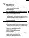
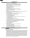
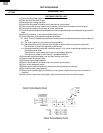
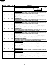
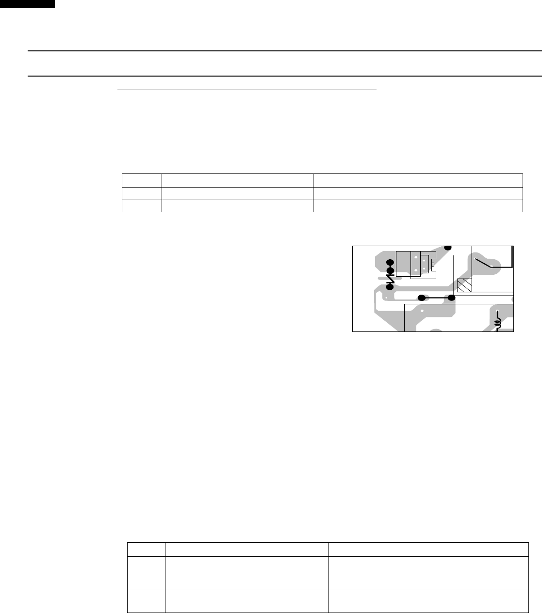
1 Only pattern at "a" is broken. *Insert jumper wire J1 and solder.
2 Pattern at "a" and "b" are broken. *Insert the coil RCILF2003YAZZ between "c" and "d".
5) Make a visual inspection of the varistor.
Check for burned damage and
examine the transformer with a tester
for the presence of layer short-circuit
(check the primary coil resistance which
is approximately 210 ohm ± 15%). If any
abnormal condition is detected, replace
the defective parts.
6) Reconnect all leads removed from components during testing.
7) Re-install the outer case (cabinet).
8) Reconnect the power supply cord after the outer case is installed.
9) Run the oven and check all functions.
2. Follow the troubleshooting guide given below, if indicator does not light up after above check and repairs
are finished.
1) Disconnect the power supply cord, and then remove outer case.
2) Open the door and block it open.
3) Discharge high voltage capacitor.
4) Disconnect the leads to the primary of the power transformer.
5) Ensure that these leads remain isolated from other components and oven chassis by using
insulation tape.
6) After that procedure, re-connect the power supply cord.
7) Follow the troubleshooting guide given below for repair.
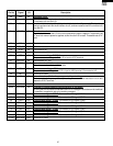
STEPS OCCURRENCE CAUSE OR CORRECTION
The rated AC voltage is not present between
1 Pin No. 1 of the 2-pin connector (A) and the Check supply voltage and oven power cord.
common terminal of the relay RY1.
2
The rated AC voltage is present at primary Low voltage transformer or secondary circuit defective.
side of low voltage transformer. Check and repair.
8) Disconnect the power supply cord, and then remove outer case.
9) Open the door and block it open.
10) Discharge high voltage capacitor.
11) Reconnect all leads removed from components during testing.
12) Re-install the outer case (cabinet).
13) Reconnect the power supply cord after the outer case is installed.
14) Run the oven and check all functions.
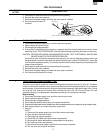
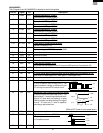
M FOIL PATTERN ON THE PRINTED WIRING BOARD TEST
To protect the electronic circuits, this model is provided with a fine foil pattern added
to the primary on the PWB, this foil pattern acts as a fuse.
TEST PROCEDURES
PROCEDURE
LETTER
COMPONENT TEST
1. Foil pattern check and repairs.
T1
AC
VRS1
OMIF
DU
CN - A
(J1)
a
b
c
d
12
XA
VH