


17
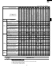
CDMOS200
DMOS200
VMOS200
CVMOS200
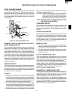
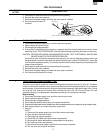
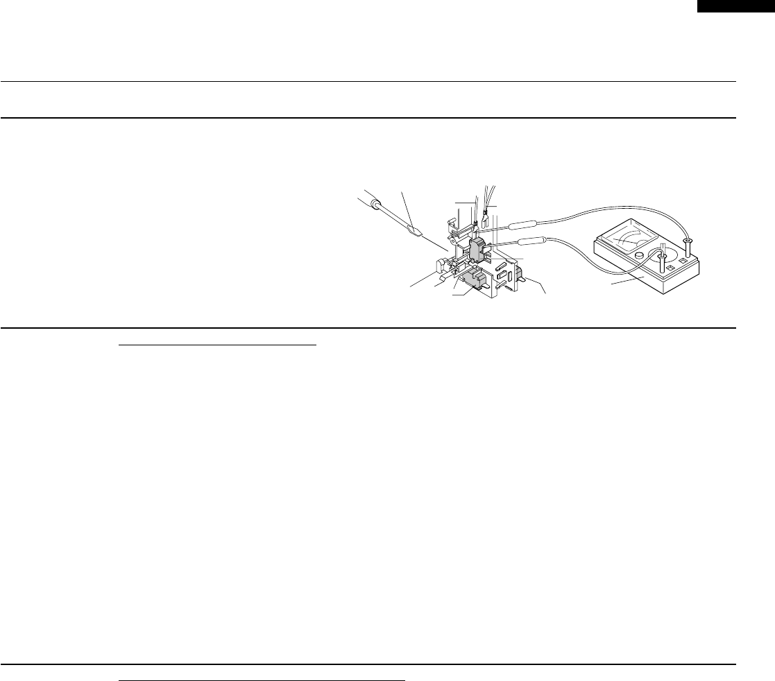
H BLOWN MONITOR FUSE TEST
TEST PROCEDURES
PROCEDURE
LETTER
COMPONENT TEST
1. Disconnect the power supply cord, and then remove outer case.
2. Open the door and block it open.
3. Discharge high voltage capacitor.
4. If the monitor fuse is blown when the door is opened, check the primary switch and monitor switch
according to the "TEST PROCEDURE" for those switches before replacing the blown monitor fuse.
CAUTION: BEFORE REPLACING A BLOWN MONITOR FUSE, TEST THE PRIMARY SWITCH AND
MONITOR SWITCH FOR PROPER OPERATION.
If the monitor fuse is blown by improper switch operation, the monitor fuse and monitor switch must
be replaced with "monitor fuse and monitor switch assembly" part number FFS-BA016/KIT, even if the
monitor switch operates normally. The monitor fuse and monitor switch assembly is comprised of a 20
ampere fuse and switch.
5. Reconnect all leads removed from components during testing.
6. Reinstall the outer case (cabinet).
7. Reconnect the power supply cord after the outer case is installed.
8. Run the oven and check all functions.
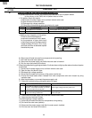
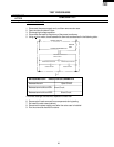
The touch control panel consists of circuits including semiconductors such as LSI, ICs, etc. Therefore,
unlike conventional microwave ovens, proper maintenance cannot be performed with only a voltmeter
and ohmmeter. In this service manual, the touch control panel assembly is divided into two units, Control
Unit and Key Unit, and also the Control Unit is divided into two units, LSI Unit and Power Unit, and
troubleshooting by unit replacement is described according to the symptoms indicated.
Before testing,
1) Disconnect the power supply cord, and then remove outer case.
2) Open the door and block it open.
3) Discharge high voltage capacitor.
4) Disconnect the leads to the primary of the power transformer.
5) Ensure that these leads remain isolated from other components and oven chassis by using insulation tape.
6) After that procedure, re-connect the power supply cord.
1. Key Unit.
NOTE ;
1) Disconnect the power supply cord, and then remove outer case.
2) Open the door and block it open.
3) Discharge high voltage capacitor.
4) Check Key unit ribbon connection before replacement.
5) Reconnect all leads removed from components during testing.
6) Re-install the outer case (cabinet).
7) Reconnect the power supply cord after the outer case is installed.
8) Run the oven and check all functions.
I TOUCH CONTROL PANEL ASSEMBLY TEST
5. Reconnect all leads removed from components during testing.
6. Reinstall the outer case (cabinet).
7. Reconnect the power supply cord after the outer case is installed.
8. Run the oven and check all
functions.
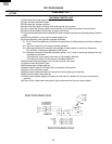
Monitor
Switch
Primary Interlock Switch
Screw Driver
Ohmmeter
RED
WHT/WHT
Secondary Interlock Switch