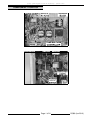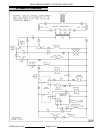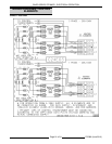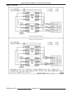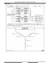
C24EO SERIES STEAMER - ELECTRICAL OPERATION
ELECTRICAL OPERATION
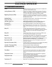
COMPONENT FUNCTION
Buzzer ................................ Creates audible signal when timed cook cycle is complete and
when a low water condition exists.
Limiting Contactor (1CON) ............... Supplies line voltage to heating element assembly. Energized
whenever Power Switch (1S) is on and High Limit Thermostat
(1TAS) and Low Water Thermostat (2TAS) are closed.
Regulating Contactor (2CON) ............. Supplies line voltage to heating element assembly. Energized
whenever Hold Thermostat (3TAS) is closed or the temperature
controller calls for heat.
Heating Element ........................ Located below water reservoir. Heats water to produce steam.
Fuses (1FU & 2FU) ...................... Protect control circuitry from over-currents.
Low Water Light (1LT) ................... Amber (AM) colored light. Lit when Low Water Thermostat
(2TAS) senses water level is too low inside steamer.
On Light (2LT) ......................... Amber (AM) colored light. Lit when Power Switch (1S) is on.
Cook Light (3LT) ....................... Red (RD) colored light. Lit when High Limit (1TAS) and Low
Water (2TAS) thermostats are closed, door is closed and timer
is set.
Relay (K1) ............................. Controls Regulating Contactor (2CON) based on input from
Hold Thermostat (3TAS) and Temperature Controller. Does not
allow Timer Motor to run while Hold Thermostat (3TAS) is
closed.
Relay (K2) ............................. Latches Power Switch (1S) circuit. Turns on Low Water Light
(1LT) and Buzzer when steamer is low on water.
Relay (K3) ............................. Controlled by Power Switch (1S). Keeps Buzzer from sounding
and Low Water Light (1LT) off when switch is in off position.
Power Switch (1S) ...................... Rocker switch that turns steamer OFF and ON (momentary on).
Switch also resets Low Water Light (1LT) and Buzzer.
Door Switch (1SW) ..................... Removes power from a portion of the steamer control circuit
when door is opened.
High Limit Thermostat (1TAS)............. Protects steamer by removing control circuit power if the heating
element assembly temperature goes above 495EF.
Low Water Thermostat (2TAS) ............ Monitors presence of water inside steamer.
Hold Thermostat (3TAS) ................. Controls temperature of cavity for pre-heat/hold mode (opens at
175E F). Disables timer countdown if cavity temperature is too
low.
Timer Motor............................ Counts cook time of product when time is dialed. Energizes
buzzer and de-energizes temperature controller when time
expires.
Temperature Control .................... Monitors temperature probe and cycles power to regulating
contactor (2CON) for steam generation.
Temperature Probe ..................... Senses cooking compartment temperature at steam vent and
sends a corresponding DC voltage back to the temperature
control (J-type thermocouple).
Transformer (1T) ....................... Steps down line voltage to 120VAC control circuit voltage.
F25386 (June 2010)
Page 16 of 24


