


— 5 —
LOCATION
The area around the broiler should be kept free and clear of all combustible materials.
ASSEMBLY
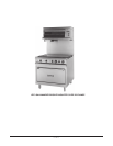
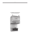
Mount the broiler to the range (the two broiler legs slide in and are mounted to the two channels
provided in the back of the range).
ELECTRICAL CONNECTIONS
WARNING: ELECTRICAL AND GROUNDING CONNECTIONS MUST COMPLY WITH THE
APPLICABLE PORTIONS OF THE NATIONAL ELECTRICAL CODE AND/OR OTHER LOCAL
ELECTRICAL CODES.
WARNING: DISCONNECT THE ELECTRICAL POWER SUPPLY AND PLACE A TAG AT THE
DISCONNECT SWITCH TO INDICATE THAT YOU ARE WORKING ON THE CIRCUIT.
VB73 and VB73R Broilers
Bring the broiler leads (A1, A2, B1, B2 in 208, 240 and 480 volt models, and X, Y, N in 220/380 or
240/415 volt models) down and through the range's burner box compartment to the circuit breakers or
the terminal block and connect them to the proper terminal. Refer to the wiring diagram of the range
(located on the kick panel), or the schematic decal on the broiler.
ESB36 Broiler
Bring the broiler leads (A1, A2, B1, B2 in 208, 240 and 480 volt models, and X, Y, N in 220/380 or
240/415 volt models) down through the wire chase located on the rear of the range, and connect the
terminal as required to the electrical supply. It may be necessary to remove the
1
/4-20 screw that retains
the wire chase to the range in order to properly feed the wires through the chase. Refer to the wiring
diagram of the range (located on the kick panel), or the schematic decal on the broiler.
VB73, VB73R and ESB36 Broilers
Broilers wired for 3-phase service may be changed to 1-phase (or vice versa) by simply relocating two
of the four broiler leads on the range's terminal block as shown in the wiring diagram of the particular
range to which the salamander broiler is mounted.
All required broiler wiring diagrams are packaged separately in a clear plastic ziplock bag and shipped
with the broiler.