


-
5 -
FLUE CONNECTIONS
Do not obstruct the flow of flue gases from the flue, located at the rear of the griddle. It is
recommended that flue gases be ventilated to the outside of the building through a
ventilation system installed by qualified personnel.
From the termination of the flue to the filters of the hood venting system, a minimum
clearance of 18” must be maintained.
Information on the construction and installation of ventilating hoods may be obtained from
the standard for “Vapor Removal from Cooking Equipment”, NFPA No. 96 (latest edition),
available from the National Fire Protection Association, Batterymarch Park, Quincy, MA
02269.
GAS CONNECTIONS
Gas supply connections and any pipe joint compound must be resistant to the
action of propane gases.
Use a ¾” NPT gas supply line for the griddle inlet, located at the rear of the griddle. All of
flexible and semi-rigid gas supply lines must comply with the applicable ANSI standard.
To ensure maximum operating efficiency, this appliance must be connected with a gas
supply line of solid pipe or a commercial type Flexible Connector with the net inside
diameter (I.D.) as large as or larger than the gas pipe inlet on this appliance. Codes
require that a gas shutoff valve must be installed in the gas line upstream of the griddle.
Prior to lighting, check all joints in the gas supply line for leaks.
Use soap and water solution. Do not use an open flame.
After checking for leaks all lines receiving gas should be fully purged to remove air.
TESTING THE GAS SUPPLY SYSTEM
When the gas supply pressure exceeds ½ psig (3.45 kPa), the griddle and its individual
shutoff valve must be disconnected from the gas supply piping system.
When the gas supply pressure is ½ psig (3.45 kPa) or less, the griddle should be isolated
from the gas supply system by closing its individual manual shutoff valve.
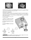
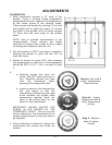
GAS PRESSURE REGULATOR INSTALLATION
This griddle is supplied with a convertible gas pressure regulator preset at 4” Water
Column (W.C.) for natural gas. No further adjustment should be required. Install the
regulator as close to the griddle on the gas supply line as possible. Make sure that the
arrow on the underside of the regulator is oriented in the direction of gas flow to the
griddle (Fig. 2 on next page) and the regulator is positioned with the vent plug and
conversion plug cover upright (Fig. 3 on next page).